



Content last revised on September 30, 2026
Preventing Spurious Faults: Surge Current and Junction Temperature Checks for MCC312-16IO1
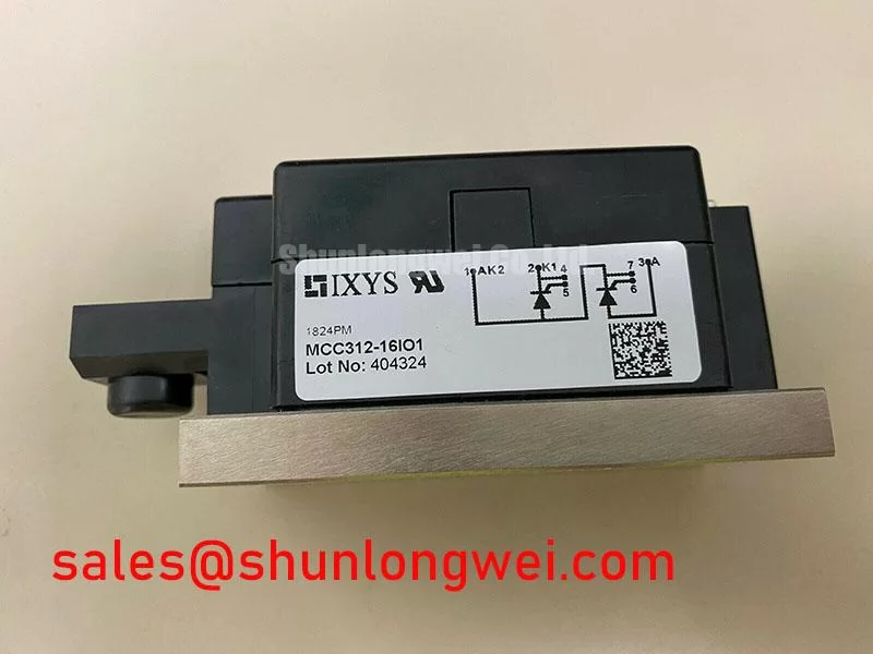
| Model | MCC312-16IO1 |
|---|---|
| Manufacturer | IXYS |
| Product category | Dual thyristor module |
| Package | Module |
| Rated voltage | 1600 V (Official Specification) |
| Rated current | 312 A (Official Specification) |
With the equipment isolated, measure resistance between the power terminals of MCC312-16IO1 in both meter polarities, then compare the readings with a known working branch. A low reading in both directions warrants further investigation, but an in-circuit measurement is not proof of a failed thyristor: snubbers, transformers, and parallel paths can influence the meter. Check each gate connection against the equipment schematic before interpreting gate-to-cathode readings.
The module’s 1600 V voltage and 312 A current ratings are Official Specifications, not substitutes for a surge-current limit. For a fault or capacitor-inrush event, the relevant checks are the specified half-cycle surge rating, its initial junction-temperature condition, and the applicable fuse I²t limit. Those values are not established by the core ratings above, so do not assign a numerical surge margin from them. As a Design Consideration, compare the recorded current waveform and protective-device clearing behavior with the complete module and fuse specifications; allow for the junction’s transient heating before reverse voltage is reapplied.
In a grid-tied static var compensator, a thyristor-switched capacitor branch is one possible integration context, subject to the branch schematic and operating duty. IEC 60747-6 Semiconductor Devices — Thyristors provides a relevant device-standard reference when checking how thyristor characteristics are defined and tested.
Assembly Integrity and Heatsink Contact for MCC312-16IO1
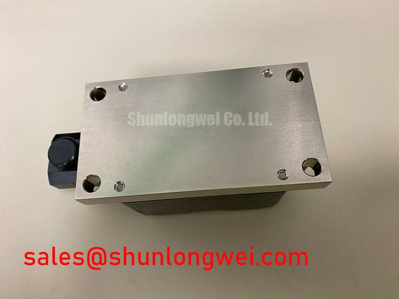
Inspect the mounting face for uneven contact marks and check the terminal hardware for looseness before returning the module to service. Poor contact can raise case temperature without leaving an obvious electrical fault at the terminals. Clean the mating surfaces, examine heatsink flatness, and check that the assembled module sits uniformly against the sink rather than rocking on an edge.
Junction-to-case thermal resistance, often written Rth(j-c), describes part of the heat path; the heatsink interface and cooling arrangement add further resistance. A numerical Rth(j-c), mounting torque, and tightening sequence have not been supplied in the core specifications, so none should be treated as an Official Specification here. As a Design Consideration, use the module drawing and the equipment’s approved fastener procedure to establish torque and sequence, and verify thermal performance under the actual current waveform. The same inspection should include cable-lug seating and clearance around the main terminals.
Field Alert: Isolate and discharge the power circuit before loosening a terminal or lifting the module from its heatsink. After reassembly, compare case temperatures and branch currents with the other installed branches under comparable operating conditions; a difference is a prompt to inspect the whole thermal and electrical path, not a diagnosis by itself.
MCC312-16IO1 Operational Boundaries: Commutation and Gate Triggering
Capture the gate pulse and the voltage across the thyristor during a suspected missed firing event. Check whether the pulse reaches the intended device at the intended point in the cycle, then inspect the gate return and connector seating. Trigger-current and trigger-voltage characteristics, commonly identified as IGT and VGT, matter to this comparison, but no model-specific values are provided in the core specifications. Pulse-train strength and timing must therefore be evaluated against the full device data and the installed controller.
A dual thyristor module should not be assessed using assumed diode reverse-recovery peak current or recovery-time figures. Thyristor turn-off and subsequent blocking depend on current commutation and the available recovery interval. As a Design Consideration, review branch current, reapplied voltage, and gate noise together when switching behavior is uncertain. Keep the gate loop arranged to limit parasitic coupling, then confirm its behavior on the operating assembly rather than prescribing a universal damping component or bias level.
Where a schematic also contains a diode module, identify its separate function before comparing switching data. The Mitsubishi Electric diode modules lineup illustrates that diode-module recovery characteristics belong to a different device category. For a broader view of power-device integration, see Future of Power Electronics; equipment life still depends on measured duty and system conditions, not a module rating alone.
MCC312-16IO1 Circuit Protection and Surge Assessment
Trace the incoming surge path on the equipment schematic and inspect the surge suppressor, snubber connections, and semiconductor fuse after a protection trip. A damaged suppressor or open snubber connection can change the voltage seen by the thyristor, while a fuse inspection alone cannot establish what peak voltage reached the module. The relevant surge-immunity test series is IEC 61000-4-5; it assesses equipment-level behavior and does not, by itself, certify this module.
As a Design Consideration, select a metal oxide varistor and RC snubber from the measured system voltage, expected transients, coordination requirements, and the thyristor’s full specifications. Verify voltage at the module terminals during controlled switching tests. Coordinate the semiconductor fuse’s clearing I²t with the applicable device limit and fault conditions rather than assuming the 312 A rating defines short-circuit protection.
For a repair substitution, compare the original schematic, terminal arrangement, mounting interface, gate-drive requirements, and complete electrical ratings. MCC225-16IO1 is a separate candidate for specification comparison, not an automatic replacement. If the equipment also uses a rectifier stage, MCD312-18IO1 can be reviewed as a separate module in that power path; its role and compatibility must be established from the circuit documentation.