Content last revised on September 20, 2026
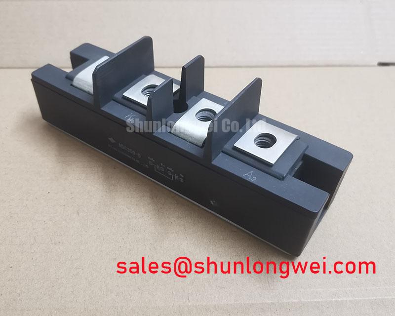
MDC6005077 IXYS 1600 V 600 A Dual Diode Module
Begin the bench check by isolating the module from every external conductor, then inspect the terminals, baseplate, and insulating surfaces before comparing its marked ratings with the soft starter design record. The IXYS MDC6005077 is a high-current dual diode module specified for demanding rectification and AC motor soft starter applications where reverse-voltage capability, surge-current tolerance, isolation, and thermal control must be assessed together.
| Parameter | Official Specification |
|---|---|
| Repetitive Peak Reverse Voltage, VRRM | 1600 V |
| RMS Forward Current, IRMS | 600 A |
| Surge Current, IFSM, 8.3 ms | 5500 A |
| Isolation Voltage, terminals to baseplate, 1 minute | 3500 VRMS |
| Operating Junction Temperature, TJ | −40°C to 150°C |
These values are Official Specification data supplied for the MDC6005077. They are not a complete application design envelope. The system engineer should confirm the complete manufacturer datasheet, including terminal configuration, forward-voltage characteristics, thermal resistance, surge-current conditions, gate or control requirements if applicable to the assembly, recommended mounting method, and any fuse coordination data before releasing a replacement into service.
For a high-voltage three-phase motor solid-state soft starter, the module may be evaluated in the power path where controlled current flow and transient suppression are required. The actual circuit position, line voltage, bypass arrangement, cooling method, and fault-clearing strategy remain system-dependent. During procurement, compare the installed part marking, electrical ratings, terminal arrangement, mechanical footprint, and insulation requirements with the original equipment documentation.
Benchtop Waveform Tuning: Mitigating Stress via Critical Rate of Rise of Off-State Voltage on MDC6005077
Start waveform work with a known-good reference assembly rather than adjusting the snubber by assumption. Confirm that the oscilloscope probe, differential measurement method, and current probe are rated for the circuit voltage and switching environment. Capture the voltage across the relevant diode path during startup, steady-state operation, bypass transfer, and shutdown. A steep off-state voltage transition can interact with layout inductance, junction capacitance, wiring capacitance, and the installed suppression network. The observation should therefore be made at the module terminals, not only at the controller output.
An RC snubber is a Design Consideration, not an automatically valid accessory for every MDC6005077 installation. The resistor and capacitor must be selected from measured transient energy, repetitive waveform behavior, capacitor pulse capability, resistor pulse loading, and the permitted leakage or standby-current budget of the soft starter. Designers should tune the network while monitoring both voltage overshoot and temperature rise. A setting that reduces a voltage spike may increase snubber dissipation or alter the current waveform, so the final choice should be verified during the complete operating cycle.
Series saturable reactors may also be considered where the system requires control of the initial current slope. Their suitability depends on line frequency, prospective fault current, operating current, reset behavior, and the desired soft-start profile. They should not be treated as a substitute for correct semiconductor fuse coordination or adequate heat removal. The 5500 A, 8.3 ms IFSM rating is an Official Specification boundary for the stated test condition; it is not permission to expose the module repeatedly to uncontrolled fault pulses.
Inspect terminal connections before interpreting a waveform. A loose power connection, uneven contact surface, oxidized hardware, or a probe connected at the wrong reference point can create measurements that appear to be semiconductor instability. Verify the complete terminal map from the original IXYS documentation because the supplied product data does not define the physical terminal arrangement. The nearby rectification stage may be reviewed alongside MSKD36-18 when checking how upstream power conversion interacts with the soft starter power path, but compatibility must be established from the system schematic rather than from product category alone.
For replacement evaluation, compare the measured voltage waveform with the 1600 V VRRM rating and account for repetitive overshoot under the actual line and load conditions. The required design margin is system-determined. Engineers should verify peak voltage, current sharing, repetitive pulse behavior, and temperature at the worst operating point before approving the assembly.
Benchtop Waveform Tuning: Mitigating Stress via Coordination of Primary Spark Gaps and MOVs on MDC6005077
Primary surge protection should be assessed as a coordinated network. A spark gap, MOV, line reactor, RC snubber, and semiconductor fuse each respond on different time scales and carry different energy duties. The MDC6005077 provides a 1600 V repetitive peak reverse-voltage specification, but that rating does not define the clamping voltage of an MOV or the let-through behavior of the complete installation. The protection engineer must examine the surge waveform at the module terminals and verify that the protective devices remain within their own certified operating limits.
For equipment evaluated against an IEC 61000-4-5 surge test, use the applicable equipment-level test plan and product safety requirements. The module itself should not be described as independently compliant with an EMC or immunity standard. Compliance is determined by the complete soft starter, including enclosure, wiring, protective earth, control electronics, surge network, and test configuration.
When selecting an MOV, engineers should consider maximum continuous operating voltage, temporary overvoltage exposure, surge-energy repetition, leakage at operating temperature, and the actual clamping voltage at the expected current. The MOV should coordinate with the spark gap so that one device does not repeatedly absorb energy intended for the other. This is an Engineering Recommendation for system evaluation, not an MDC6005077 factory specification.
The bench sequence should include an unpowered insulation inspection, a low-energy control check, and a controlled high-voltage test using equipment appropriate for the assembly. Record the line-to-line and line-to-baseplate behavior separately. The stated terminal-to-baseplate isolation value is 3500 VRMS for 1 minute, an Official Specification condition; the test voltage, ramp method, fixtures, clearances, and acceptance criteria for a finished soft starter must be defined by the responsible safety engineer and applicable standards.
Field Alert: Disconnect and discharge the soft starter before removing probes, cables, MOVs, or the MDC6005077, because suppression components can retain hazardous energy after line power is removed.
During a replacement, do not assume that a visually similar dual diode module has the same current path or terminal polarity. Trace each conductor to the schematic, label the removed connection, and verify diode orientation with an appropriate isolated test method. If an alternative device is being assessed for service continuity, the TT570N16 may be reviewed as a separate device for comparison, subject to confirmation of voltage, current, package, thermal, and terminal requirements.
Transient Dynamics & Electrical Design: Baseplate Thermal Resistance on MDC6005077
Thermal verification begins with the mechanical stack, not the fan rating. Clean the heatsink contact area, inspect the baseplate for distortion or contamination, and confirm that the mounting surface is flat enough for the equipment design. Apply the approved thermal interface material consistently and avoid allowing excess compound to migrate toward insulation barriers or terminal hardware. The objective is stable, uniform heat transfer without bending the module body or concentrating pressure at one edge.
The MDC6005077 operating junction-temperature specification is −40°C to 150°C. This range is an Official Specification, but it does not by itself establish the permissible continuous current in a particular enclosure. The actual current capability depends on forward losses, duty cycle, ambient temperature, heatsink performance, airflow, thermal interface quality, and the complete power-sharing arrangement. Engineers should measure case or heatsink temperature at the defined reference location and correlate it with the electrical waveform.
Where a clamped or pressure-mounted heatsink is used, the required pressure and fastening sequence must follow the manufacturer’s mechanical instructions and the equipment assembly drawing. Do not invent a torque value from a generic bolt size. A torque figure is only meaningful when the thread, washer arrangement, lubricant condition, clamping method, and module construction are known. For double-sided cooling, verify both thermal interfaces and confirm that the mechanical assembly does not twist the baseplate or load the terminals.
Temperature testing should cover startup, acceleration, bypass transition, repeated starts, steady loaded operation, and abnormal but permitted line conditions. Record the temperature trend rather than relying on a short initial reading. A rising trend may reflect insufficient heatsink capacity, uneven interface contact, excessive current concentration, switching transients, or an inaccurate sensor location. These possibilities require measurement and comparison with a known-good assembly; they should not be reduced to a single presumed failure cause.
The 600 A RMS forward-current rating is an Official Specification, not a universal promise of 600 A in every soft starter enclosure. Confirm the waveform’s RMS value, crest behavior, conduction angle, cooling conditions, and repetition rate. Phase-controlled rectification can produce input-current distortion and higher-order harmonics, so the complete installation should be evaluated for power-quality impact using the applicable site and equipment requirements. The MDC6005077 should be considered as one element in that assessment.
For broader power-semiconductor integration work covering gate-drive coordination, thermal management, and circuit topology, consult the IGBT Design & Integration guide. Its subject matter is broader than this diode module, so any design rule must still be checked against the MDC6005077 documentation and the actual soft starter topology.
Assembly Integrity & Layout Architecture: Implementing Fuse Total Clearing I2t versus Device Melt for MDC6005077
Fault protection should be verified from the complete current path: supply impedance, contactor or bypass hardware, semiconductor fuse, busbar, module terminals, and the short-circuit location. The available product information confirms the MDC6005077 surge-current rating of 5500 A for 8.3 ms, but it does not provide a fuse coordination table or a device-specific I2t withstand value. Those figures must be obtained from the applicable manufacturer documentation before a fuse is selected or a fault-clearing claim is made.
When comparing a semiconductor fuse with the module, use the fuse’s pre-arcing and total-clearing I2t data under the prospective fault current and system voltage. The comparison must include the fuse manufacturer’s test conditions, temperature correction, wiring inductance, fault power factor, and the actual current path through the dual diode structure. A fuse that clears quickly in one circuit may behave differently in a high-inductance soft starter installation.
Do not use the 5500 A IFSM value as a substitute for total-clearing coordination. The surge specification describes a defined non-repetitive test condition, while a short-circuit event may involve a different waveform, duration, starting angle, current asymmetry, and thermal recovery condition. The responsible engineer should calculate or obtain the complete coordination data, then validate it through a controlled test plan suitable for the equipment voltage and fault energy.
Layout has a direct effect on fault stress. Keep the high-current path compact, use appropriately rated conductors and busbars, control stray inductance where practical, and prevent the protection network from routing destructive energy through control wiring. Terminal joints should be inspected for flat contact, correct hardware order, and secure retention after thermal cycling. The isolation requirement of 3500 VRMS for one minute between terminals and baseplate also requires suitable spacing, insulation barriers, contamination control, and test fixtures in the finished assembly.
Before energizing a repaired soft starter, perform a documented visual inspection, terminal continuity review, isolation test under the approved procedure, low-voltage functional check, and controlled current test. Confirm that the three phases share the intended electrical path and that bypass operation does not leave an unexpected current route through the diode module. The IPC Association Connecting Electronics Industries provides industry resources relevant to electronic assembly workmanship, while the equipment manufacturer remains the authority for the specific module installation and acceptance procedure.
For procurement and field replacement, record the MDC6005077 part marking, the original terminal arrangement, the measured assembly dimensions, the insulation test result, and the operating waveform. A technically suitable replacement decision requires agreement across electrical ratings, mechanical fit, thermal interface, protection coordination, and system verification rather than a current-rating comparison alone.