

Content last revised on November 11, 2026
Transient Dynamics & Electrical Design: AC-to-DC Transfer Characteristics on MDST2001662
Isolate the rectifier assembly, verify that stored energy has discharged, and disconnect parallel current paths before checking the MDST2001662 with a multimeter. Record main-terminal readings in both polarities against the circuit diagram; a low reading through an attached snubber or load does not establish a module fault. Inspect terminal seating, mounting surfaces, and gate connections before disturbing the original wiring.
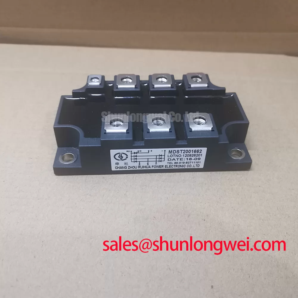
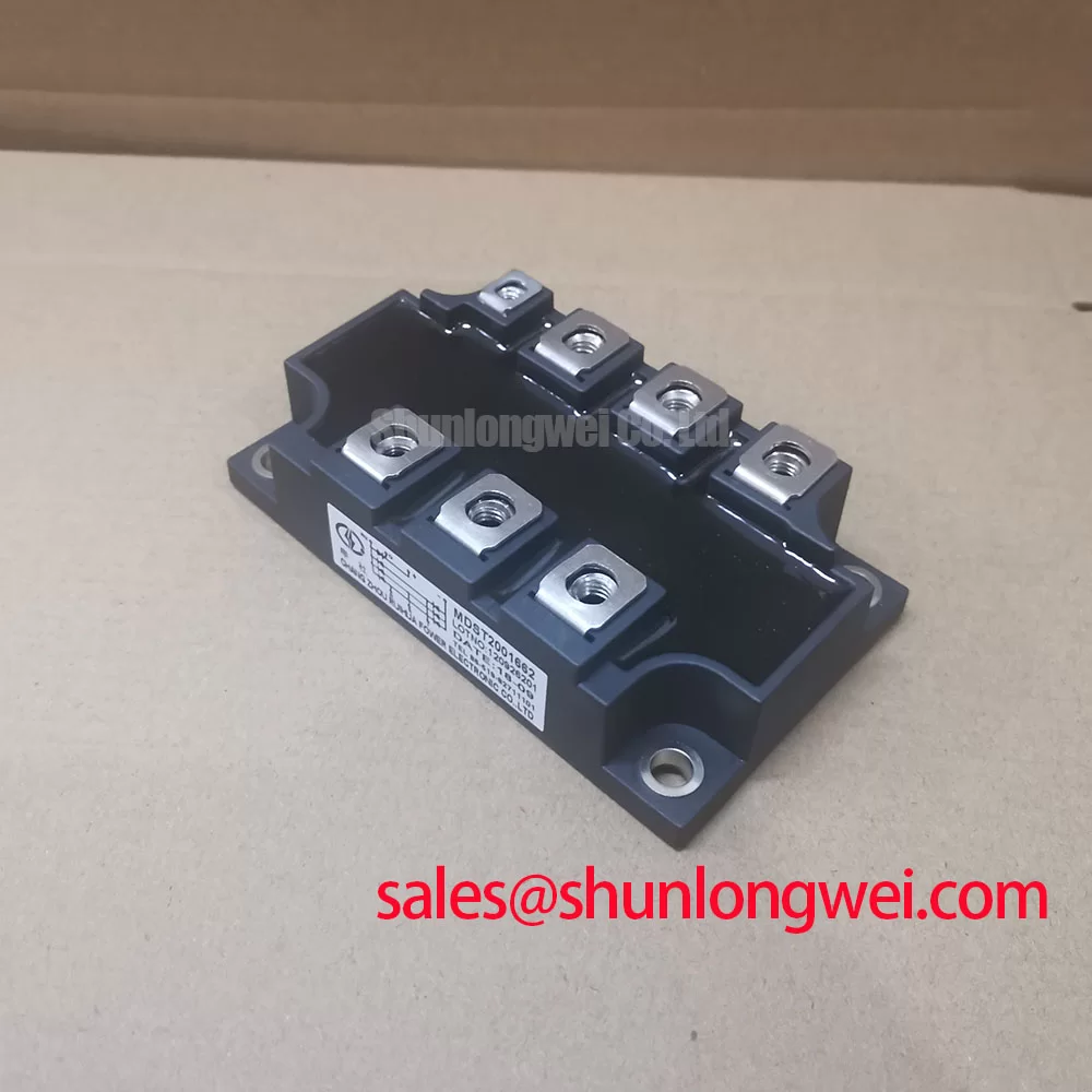
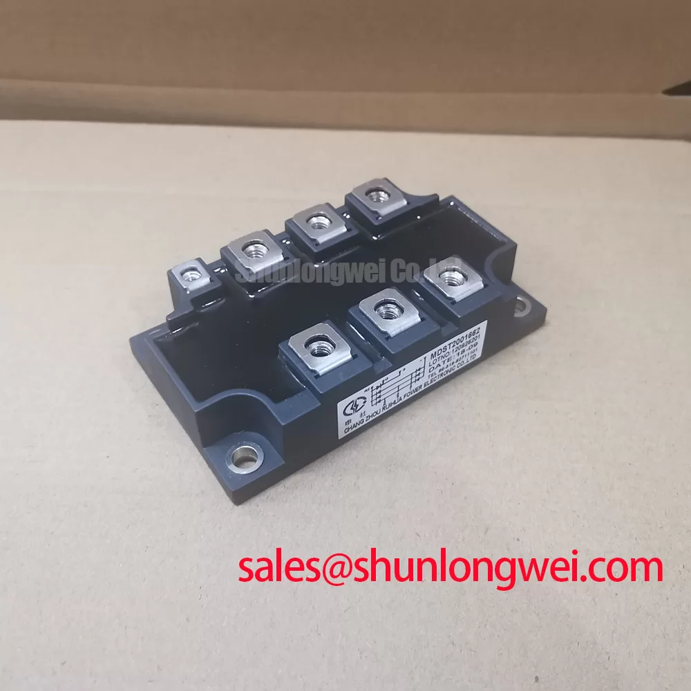
The MDST2001662 is a Bridge Rectifier Module from SanRex (Sansha Electric), with a Thyristor / Diode Module configuration. Its supplied factory ratings are Repetitive Peak Reverse Voltage (VRRM): 1600.0 V and Average On-State Current (IT(AV)): 200.0 A. These electrical identities matter: reverse blocking voltage is not an IGBT collector-emitter rating, and average on-state current is not a surge-current specification.
Compare the firing command with the actual AC phase reference and rectified output before attributing a low DC voltage to the power module. Design Consideration: changing the firing angle changes the conduction interval, but the resulting transfer characteristic depends on the complete bridge arrangement, load continuity, and any freewheeling path. A universal firing-angle conversion curve would therefore misrepresent this module without its surrounding circuit.
During a controlled firing-angle sweep, record average output voltage, current continuity, and input-current waveform together. Delayed firing can reduce average DC output while worsening input power factor through displacement and waveform distortion. Separate those effects when assessing reactive-power demand; the controller setting alone does not describe what the supply experiences. Use appropriately rated isolated instrumentation and the equipment’s approved commissioning procedure.
Trace AC inputs, DC connections, and each thyristor gate return against the assembly drawing rather than assigning terminals from package appearance. For an associated rectification-stage comparison involving DH2F200N4S, establish its circuit role independently; the link does not imply a matched companion or interchangeable terminal arrangement.
Engineers evaluating this module for a medium-frequency induction melting or hardening furnace power supply should check the existing controlled-rectifier arrangement, cooling assembly, and firing controller together. Compatibility depends on that equipment interface, not simply the headline current and voltage.
Transient Dynamics & Electrical Design: Sinusoidal 10 ms Half-Cycle Surge Current on MDST2001662
Check the protection record for the actual fault waveform before comparing it with a sinusoidal half-cycle surge test. Design Consideration: a surge rating applies to defined pulse duration, initial junction temperature, and subsequent blocking conditions. A 10 ms test description does not establish the MDST2001662 surge limit, and its 200.0 A average rating cannot substitute for ITSM.
Use the following identity and replacement-assessment table when comparing the installed module with MDS250A1600V. The reference model requires its own documented electrical and mechanical checks before substitution.
| Parameter | MDST2001662 factory specification | MDS250A1600V comparison requirement |
|---|---|---|
| Part Number | MDST2001662 | MDS250A1600V |
| Manufacturer | SanRex (Sansha Electric) | Consult datasheet |
| Repetitive Peak Reverse Voltage (VRRM) | 1600.0 V | Consult datasheet |
| Average On-State Current (IT(AV)) | 200.0 A | Consult datasheet |
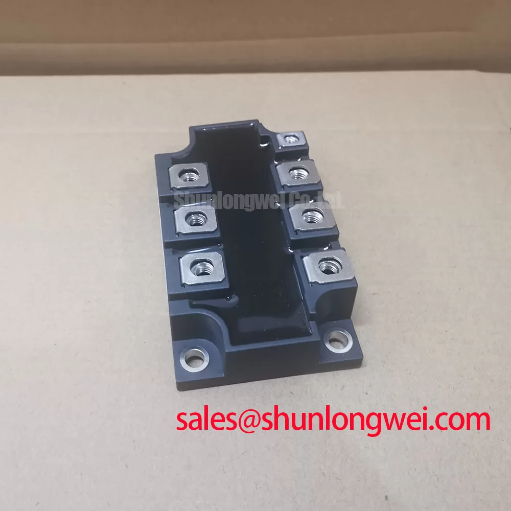
| Package | SanRex Power Module | Compare outline and terminal positions |
| Configuration / Topology | Thyristor / Diode Module | Compare internal circuit diagram |
| Surge, fuse coordination, and mounting limits | Consult datasheet | Consult datasheet |
For fuse coordination, compare total clearing I²t and peak let-through current with the semiconductor limits under the applicable fault conditions. Include prospective current and circuit voltage in that assessment. After a surge, assess junction heating and the blocking-voltage recovery conditions before authorizing another firing attempt; a cold resistance check cannot establish the remaining thermal margin.
Inspect heatsink flatness and remove displaced thermal compound before remounting. Engineering Recommendation: apply the specified thermal-interface material uniformly and tighten mounting and power-terminal fasteners using their respective documented procedures. Field Alert: Do not apply terminal-bolt torque to baseplate fasteners or compensate for poor contact by overtightening.
Transient Dynamics & Electrical Design: Gate Trigger Current Dynamics on MDST2001662
Measure the firing pulse at the gate and its associated cathode return, not only at the controller output. Design Consideration: cable impedance, return routing, and driver loading can alter the pulse delivered to the thyristor. Compare pulse amplitude, rise behavior, duration, and repetition with the device’s trigger requirements and the controller specification.
Keep gate-trigger current IGT, gate-trigger voltage VGT, latching current, and holding current distinct. The pulse’s sustaining portion must support reliable turn-on until anode current establishes conduction; holding current describes continued conduction afterward. Multi-pulse firing can support particular load conditions, but pulse repetition and gate dissipation require coordinated verification rather than an assumed strong-trigger setting.
For cold screening, isolate the gate circuit and compare gate-to-cathode behavior with equivalent channels using the same meter polarity. Treat differences as investigation leads, not definitive failure classifications. An ordinary multimeter does not reproduce blocking-voltage stress or establish reliable thyristor triggering.
Inspect the RC snubber connections and component condition when investigating unintended firing or commutation disturbances. Engineering Recommendation: assess voltage rise and overshoot at the module terminals under representative operation, then determine suppression requirements from the measured circuit behavior. The Switching loss Application Guide provides broader semiconductor-loss context; use the MDST2001662 device limits and equipment test procedure for acceptance decisions.