
Content last revised on September 10, 2026
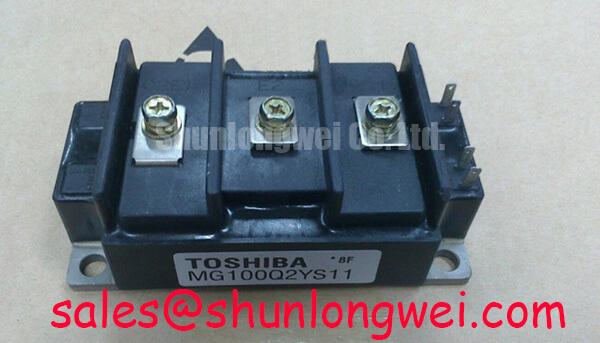
Toshiba MG100Q2YS11 Dual IGBT Module: Technical Analysis
Introduction & Highlights
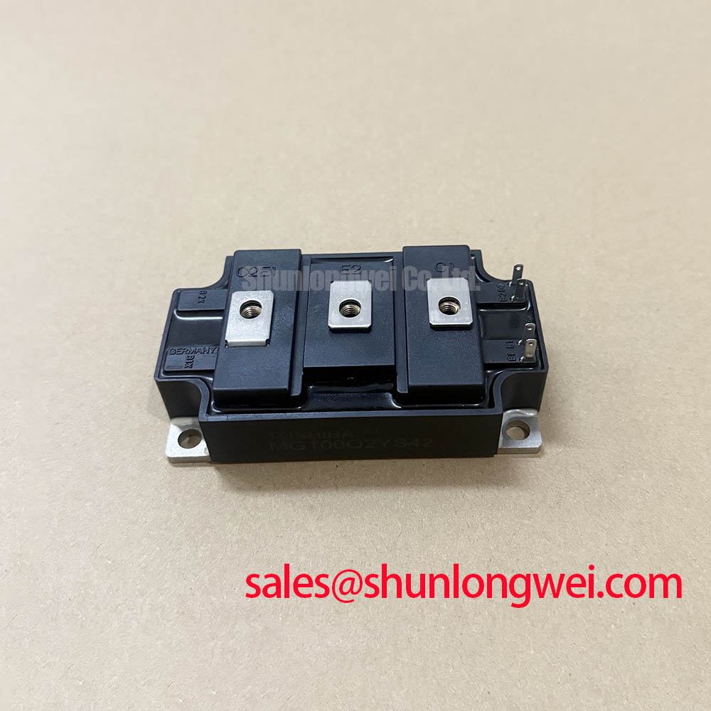
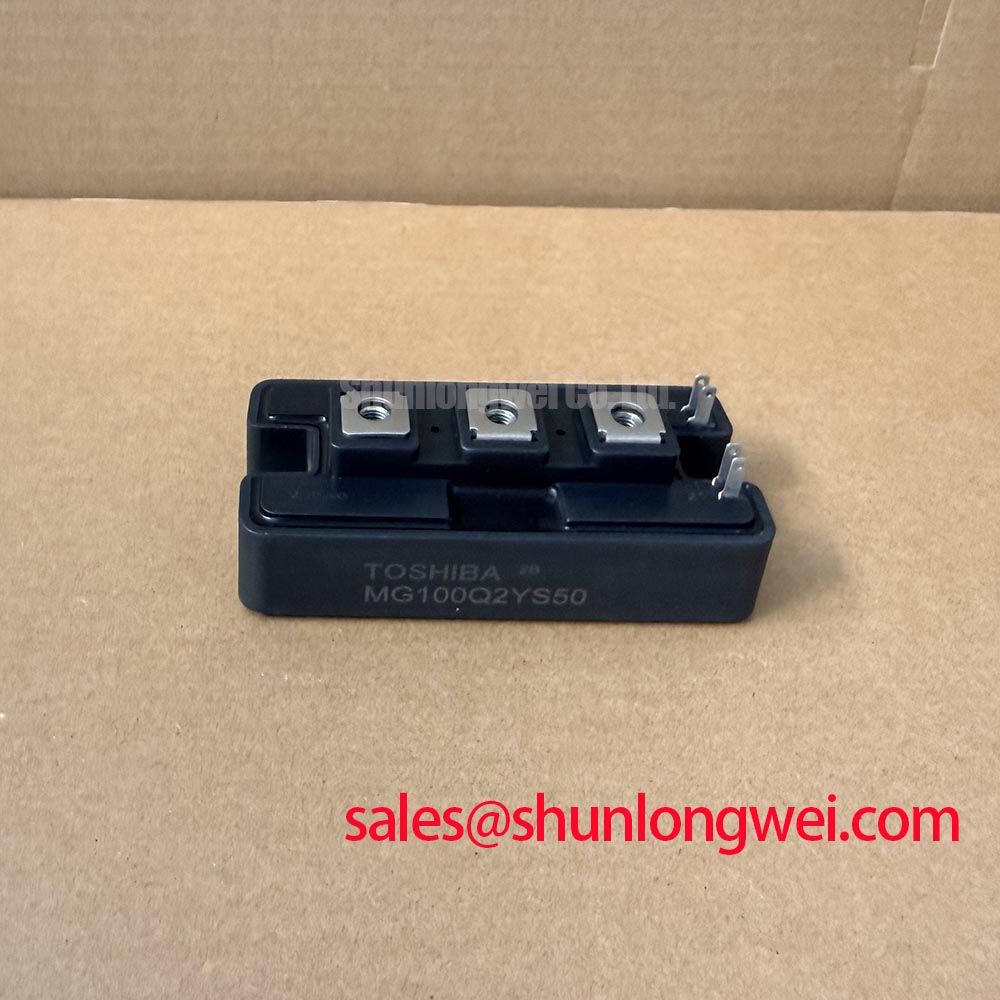
How can power electronics designers eliminate thermal bottlenecks in high-frequency half-bridge switching circuits while maintaining galvanic isolation? The Toshiba MG100Q2YS11 provides an integrated half-bridge switching stage with an isolated case, ensuring stable thermal performance under heavy cycling. This module is rated at 1200V and 100A, with a collector power dissipation of 800W. Key benefits include low saturation loss and a high 2500V isolation voltage. For industrial motor drives prioritizing thermal margins, this 1200V 100A module is the optimal choice.
Frequently Asked Questions
Addressing Design Concerns and Electrical Durability
How does the Rth(j-c) of 0.156 °C/W for the transistor stage affect thermal design?
A low thermal resistance of 0.156 °C/W allows efficient heat transfer from the junction to the case. This minimizes thermal buildup and reduces the required size of the external heatsink to support high power densities.
How does the fall time (tf) of 0.3µs impact high-speed switching designs?
The typical fall time of 0.3µs limits turn-off losses (Eoff). This is essential for controlling switching losses when operating at carrier frequencies up to 20 kHz in inductive load applications.
What is the practical benefit of the 2500V isolation voltage rating?
The 2500V isolation rating between the internal active electrodes and the copper baseplate allows multiple modules to be mounted on a shared heatsink without separate insulation sheets, simplifying system packaging.
What is the recommended gate resistance (RG) for the MG100Q2YS11?
A standard gate resistance of 9.1 Ω is typical for testing. Modifying this value helps designers balance switching speed and overvoltage spikes caused by stray inductance in the busbar.
How does the 2.7V maximum collector-emitter saturation voltage impact overall system efficiency?
A low VCE(sat) of 2.7V at 100A minimizes conduction losses during the ON-state. In high-duty-cycle operations, this reduces active cooling requirements and thermal stress on the packaging.
Key Parameter Overview
Decoding the Specs for Enhanced Thermal Reliability
Think of the Collector-Emitter Saturation Voltage as the electrical friction of a water valve. Just as a valve with high friction causes water pressure to drop and generate heat, a high VCE(sat) drops voltage and generates thermal losses in the silicon die.
| Parameter & Symbol | Value | Engineering Significance & Value |
|---|---|---|
| Collector-Emitter Voltage (VCES) | 1200V | Prevents electrical breakdown in typical 400V/480V AC line voltage operations. |
| Collector Current (IC, DC) | 100A | Enables continuous current handling under heavy industrial loads. |
| Collector Power Dissipation (PC) | 800W | Represents the maximum power the transistor stage can dissipate at Tc = 25°C. |
| Collector-Emitter Saturation Voltage (VCE(sat)) | 2.7V (Max) | Defines conduction loss; lower values mean cooler operation at full load. |
| Fall Time (tf) | 0.3µs (Typ) / 0.6µs (Max) | Low fall time directly translates to reduced turn-off switching losses. |
| Isolation Voltage (Visol) | 2500V (AC, 1 min) | Ensures electrical safety and permits mounting on a common heatsink. |
| Thermal Resistance (Rth(j-c)) | 0.156 °C/W (IGBT) / 0.5 °C/W (Diode) | Determines heat extraction efficiency from junction to case. |
Download the MG100Q2YS11 datasheet for detailed specifications and performance curves.
Technical & Design Deep Dive
A Closer Look at the Isolated Half-Bridge Architecture
The MG100Q2YS11 incorporates two N-channel IGBTs connected in a half-bridge topology, paired with fast recovery free-wheeling diodes. To understand the thermal interface, think of thermal resistance like thermal insulation. A lower rating of 0.156 °C/W acts as a super-conductive thermal highway, allowing heat to escape to the heatsink almost instantly, similar to how a copper rod conducts heat much faster than a wooden one.
This design prevents localized hot spots that typically limit the lifespan of power electronics. Designers must coordinate gate drive layout to prevent cross-conduction in half-bridge configurations. Choosing a proper gate drive topology, comparing IGBT vs MOSFET vs BJT characteristics, helps in optimizing drive parameters.
What is the primary benefit of the half-bridge configuration? It minimizes loop inductance and simplifies gate driver routing. What is the maximum junction temperature rating? The module operates safely at junction temperatures up to 150°C.
The module is built for industrial settings requiring high reliability and low electromagnetic interference (EMI). Incorporating the isolated electrode packaging reduces system complexity, as it eliminates the need for external isolation barriers.
Application Scenarios & Value
Achieving System-Level Benefits in High-Power Motor Control
In high-power industrial applications, such as a motor control system driving heavy conveyor belts, starter currents pose a major challenge. The initial surge during startup can cause catastrophic failure if it exceeds the module's safety parameters. The MG100Q2YS11 addresses this issue with a pulsed collector current rating (ICP) of 200A for 1 ms, allowing it to absorb start-up transients within its Safe Operating Area (SOA) without damage.
This capability is crucial for systems designed under strict industrial regulations like the IEC 61800-3 standard for a Variable Frequency Drive (VFD). Integrating this module simplifies inverter assembly, providing a reliable alternative to discrete layouts. Engineers looking for more detailed integration practices can consult the in-depth analysis of IGBT modules.
While this 100A module is well-suited for medium-scale drive systems, systems requiring larger current handling may utilize the related MG150Q2YS50 for a higher nominal current of 150A, or the high-power MG400Q2YS60A for applications needing up to 400A switching capacity.
When selecting these modules, engineers must account for the trade-offs between switching speeds and thermal dissipation to optimize system reliability over a ten-year operational lifespan.