Content last revised on September 10, 2026
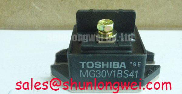
MG30V1BS41 Toshiba IGBT Module: 1700V 30A Half-Bridge Power Switch
The MG30V1BS41 delivers high-voltage half-bridge switching capability with isolated packaging, enabling industrial-grade motor control and power conversion under severe electrical stress.
Top Specs: 1700V | 30A | 500W
- Isolated package simplifies heatsink mounting.
- High input impedance optimizes gate drive.
With fully isolated electrodes, the module eliminates the need for external ceramic insulators, directly resolving design challenges regarding thermal coupling and space constraints. For 480V or 600V industrial motor drives prioritizing electrical isolation, this 1700V 30A module is the optimal choice.
Application Scenarios & Value
Mitigating High-Voltage Stress in Demanding Industrial Drives
Engineers often face the daunting challenge of transient voltage spikes when operating 480V or 600V industrial three-phase motors. Standard 1200V IGBTs may lack sufficient voltage headroom under regenerative braking conditions, leading to unexpected device failures. The MG30V1BS41, with its robust 1700V collector-emitter voltage rating, offers a massive safety margin, ensuring reliability in industrial variable frequency drive (VFD) systems and high-frequency inverter applications.
Consider a heavy conveyor motor in an automated factory. During deceleration, the motor acts as a generator, dumping energy back into the DC bus and causing dramatic voltage surges. By using a 1700V module, design engineers can safely absorb these spikes without requiring oversized, expensive snubber networks. Furthermore, the 30A continuous collector current rating comfortably manages the startup surge current of fractional and low-horsepower motors. For systems requiring higher power output, the related MG150Q2YS50 offers a 1200V rating at 150A to accommodate higher loads.
Technical Deep Dive
Inside the Half-Bridge Isolated Packaging and Switching Physics
What is the configuration of the MG30V1BS41? It integrates a complete isolated half-bridge in a single power module. What is the maximum power dissipation? It can safely dissipate up to 500W at room temperature.
At the physical level, the MG30V1BS41 integrates a complete half-bridge topology. This dual-IGBT configuration is highly optimized for bridge rectifiers and chopper circuits. Think of the isolated gate structure as a high-precision hydraulic valve. A small control voltage applied at the gate terminal acts as a minor twist of the valve knob, seamlessly managing a massive electrical current of 30A flowing from the collector to the emitter. Because of this high input impedance, driving this module requires minimal current, reducing the complexity of the gate drive circuit.
Thermal management is another core triumph of this module. In high-power modules, isolating the electrical contacts from the mounting base plate is vital. The isolated package design works like double-paned safety glass; it provides a highly reliable thermal path while maintaining complete electrical isolation up to high voltages. This eliminates the need for delicate external ceramic insulating pads, allowing direct mounting onto the system heatsink. This layout minimizes the thermal resistance, allowing the module to safely dissipate up to 500W of power at a junction temperature of 150°C.
To fully optimize these switching states, designers can benefit from decoding IGBT datasheets to balance gate resistance with switching losses. Achieving rapid fall times of 1.5 µs minimizes the turn-off energy loss, which directly enhances system efficiency in high-frequency power electronics.
Key Parameter Overview
Functional Breakdown of Key Electrical and Thermal Ratings
| Absolute Maximum Ratings | ||
|---|---|---|
| Parameter | Symbol | Value / Rating |
| Collector-Emitter Voltage | VCES | 1700 V |
| Continuous Collector Current (Tc = 25°C) | IC | 30 A |
| Pulsed Collector Current | ICP | 60 A |
| Gate-Emitter Voltage | VGES | ±20 V |
| Collector Power Dissipation (Tc = 25°C) | PC | 500 W |
| Thermal & Mechanical Specs | ||
| Operating Junction Temperature | Tj | -40 to +150 °C |
| Storage Temperature Range | Tstg | -40 to +125 °C |
| Isolation Voltage | Visol | Isolated Baseplate |
| Switching Characteristics (Typical) | ||
| Fall Time | tf | 1.5 µs |
| Diode Reverse Recovery Time | trr | 0.3 µs |
Frequently Asked Questions
Direct Technical Answers for Power System Designers
How does the 1700V rating of the MG30V1BS41 compare to standard 1200V modules in 480V AC motor drives?
In 480V AC systems, the peak DC bus voltage can exceed 680V under regenerative braking. While 1200V modules are often used, they leave little safety margin against transient voltage surges. A 1700V rated module like the MG30V1BS41 provides over 1000V of headroom, significantly preventing overvoltage failures in harsh industrial environments.
What are the practical benefits of the isolated package structure of the MG30V1BS41 during multi-module installation?
Because the electrical electrodes are completely isolated from the outer metal baseplate, multiple modules can be mounted directly onto a single, shared heatsink. This eliminates the need for fragile thermal interface pads, optimizing thermal resistance and saving significant physical footprint within the inverter cabinet.
How do the typical 1.5 µs fall time and 0.3 µs reverse recovery time affect the selection of dead-time in my controller?
The 1.5 µs fall time requires careful controller programming to avoid shoot-through currents in the half-bridge configuration. Engineers should set a robust dead-time of at least 2.5 to 3.0 µs in their control algorithms. To ensure proper module operation, you can learn how to test an IGBT module with a multimeter to verify gate health and emitter-collector pathways.
For engineering teams designing high-reliability motor control systems, securing hard-to-find components like the MG30V1BS41 is critical for maintaining industrial machinery uptime. Contact our technical sales team today to request a quote or verify available inventory for your manufacturing and repair needs.