
Content last revised on September 26, 2026
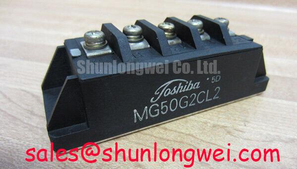
With the DC link isolated and discharged, compare the installed module’s terminal markings and mounting footprint with the replacement documentation before measuring its cold-state terminal resistance. For MG50G2CL2, the supplied official specifications identify a 1200 V voltage rating, a 50 A current rating, and a Toshiba Module package. These are Official Specification values, not a complete interchangeability check: the original datasheet and equipment drawings are still needed to confirm terminal assignments, mounting dimensions, and operating limits.
Assembly Integrity & Layout Architecture: Desaturation Detection for MG50G2CL2
A desaturation circuit supervises the IGBT’s collector-to-emitter voltage while the gate driver commands conduction. As a Design Consideration, it can help distinguish an abnormal high-voltage conduction event from normal switching behavior, but its response depends on the driver, sensing network, blanking interval, and fault logic. The supplied MG50G2CL2 data do not establish a short-circuit withstand time or a required detection threshold. Designers should therefore obtain the applicable Toshiba protection limits before setting a trip response; a generic detection-time target must not be treated as this module’s rating.
During integration, trace the desaturation sense path and gate return on the actual driver board. Keep the sensing path clear of noisy power-current routes, and check that its electrical spacing follows the equipment’s insulation design. Confirm how the driver inhibits subsequent pulses after a trip. A controlled, staged turn-off may reduce inductive overvoltage during fault interruption, but its suitability must be established against the measured collector-voltage peak and the module’s documented limits. TI’s isolated gate-driver information provides useful context for evaluating driver-side protection features; it does not define MG50G2CL2-specific settings.
For a repair investigation, record the fault indication before clearing it, then compare the desaturation sense waveform, gate command, and collector-voltage behavior with a known-good channel where one is available. A trip during an otherwise ordinary transition may reflect sensing noise or timing, while a genuine overcurrent remains possible. Neither interpretation should be assigned from the fault flag alone.
Transient Dynamics & Electrical Design: Commutation Loop Inductance on MG50G2CL2
In a switching leg, the DC-link capacitor, conductors, module terminals, and return path form the commutation loop. As an Engineering Calculation, turn-off collector voltage can be considered as the DC-link voltage plus the voltage induced by loop inductance as current changes. This explains why busbar geometry and capacitor placement matter even when the steady DC-link voltage is below the 1200 V Official Specification rating. It does not supply a universal inductance target or snubber value for MG50G2CL2.
As a Design Consideration, place opposing current paths close together and maintain comparable geometry across corresponding switching legs. Select a snubber only after measuring the switching waveform in the installed assembly: its capacitance and physical connection affect both overshoot and loss. Probe at appropriate module terminals with a measurement arrangement suited to fast transitions, then evaluate peak voltage under the system’s relevant current, temperature, and DC-link conditions. An unexpectedly high peak warrants inspection of the capacitor connections, busbar joints, and gate-drive waveform before attributing the behavior to the module.
Complementary gate commands also require an interlock and sufficient dead time to prevent simultaneous conduction. The necessary timing is system-determined because driver propagation delay, switching behavior, and operating conditions all contribute. Check both gate waveforms at the installed assembly rather than relying solely on controller settings. 💡 Pro Tip: Keep the outgoing and return busbar paths geometrically balanced, then verify turn-off voltage margin with switching measurements before accepting a layout change.
When reviewing associated power stages, MG150Q1JS40 may be included in a separate complementary-stage component comparison, subject to its own datasheet and the equipment schematic. Its model designation alone does not establish a rectifier function or electrical compatibility with MG50G2CL2.
MG50G2CL2 Operational Boundaries: Evaluating Transient Thermal Impedance
The 50 A Official Specification current rating should not be interpreted as permission to run every pulse or continuous operating point at that current. Current rating conditions, case temperature, cooling arrangement, switching loss, and permissible junction temperature must be checked in the original Toshiba documentation. The supplied specifications do not include an MG50G2CL2 transient thermal-impedance curve or thermal-model coefficients, so a numerical pulsed-overload junction-temperature margin cannot be calculated responsibly here.
For an equipment assessment, capture the current waveform and switching frequency, identify the heat-sink and mounting arrangement, and inspect the contact surfaces for seating problems. Use documented device loss and thermal data, if available, to evaluate the temperature excursion over the actual pulse sequence. A multi-RC thermal model is useful only when its coefficients correspond to the device and its boundary conditions; coefficients borrowed from another module would turn a calculation into an unsupported estimate.
Thermal cycling deserves particular attention if the module is being evaluated for a bidirectional battery DC-DC stage in a microgrid energy-storage system. Charging and discharging profiles can produce different loss patterns, so compare both directions under the equipment’s intended controls. Cooling improvements may reduce temperature excursions, but no service-life extension can be quantified without applicable test data. For broader discussion of cooling approaches, see The Advanced Thermal Management Revolution; its techniques should not be assumed to describe the internal construction of MG50G2CL2.
Field Diagnostics & Commissioning: Parallel Current Sharing in MG50G2CL2 Topologies
Before operating modules in parallel, verify that the equipment schematic actually specifies that arrangement and that each installed position has the intended gate-drive and power connections. The supplied MG50G2CL2 specifications do not establish a collector-emitter saturation-voltage temperature coefficient across the operating range. Consequently, positive-temperature-coefficient static sharing must not be assumed without the relevant Toshiba curves. Dynamic sharing also depends on gate-path and power-path impedance, not just nominal module ratings.
As a Design Consideration, compare the physical length and routing of corresponding gate loops and power paths, then measure branch currents during controlled commissioning. Differences in turn-on or turn-off current may prompt inspection of gate connections, driver outputs, busbar joints, and cooling contact. Compare waveforms under the same operating conditions; a single current reading cannot distinguish a drive imbalance from a thermal or connection issue.
For a commercial string-inverter or microgrid repair, document the original module’s terminal map and the equipment’s protection behavior before assessing another part. MG100Q1ZS40 is a separate Toshiba part that can be placed on a sourcing comparison list, but substitution requires independent checks of ratings, circuit configuration, footprint, gate-drive requirements, and thermal fit. During recommissioning, increase operating load under the equipment’s approved procedure while observing branch currents, gate signals, and switching-voltage peaks against the design limits.