Content last revised on June 12, 2026
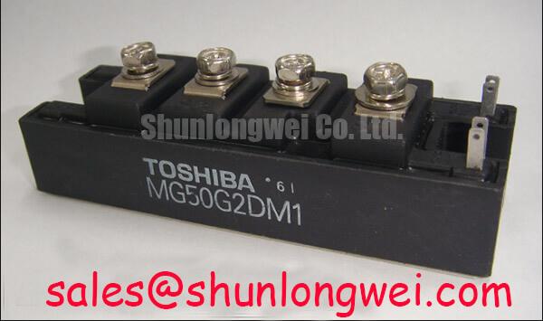
MG50G2CL3 Toshiba 600V 50A High-Power GTR Darlington Transistor Module
The Toshiba MG50G2CL3 is a high-gain Darlington bipolar transistor (GTR) module engineered for efficient low-frequency power switching in industrial environments. Featuring a 600V collector-emitter voltage and a 50A continuous collector current rating, this module integrates two isolated transistors with fast-recovery freewheeling diodes. How does the Darlington structure benefit power stages? It maximizes current gain while maintaining low drive power requirements. For industrial motor drives requiring a 600V Vceo margin, the MG50G2CL3 remains a benchmark for low-frequency switching reliability.
Application Scenarios & Value
Optimizing Performance in Industrial Low-Frequency Switching
Engineers often face the challenge of managing high inductive loads in older Variable Frequency Drive (VFD) architectures or specialized DC choppers where switching frequencies are relatively low. The MG50G2CL3 addresses this by providing a high DC current gain (hFE) of at least 100, which significantly reduces the complexity and power consumption of the base drive circuit. In systems like UPS (Uninterruptible Power Supplies) or AC motor drives, the isolated package allows multiple modules to be mounted on a single heatsink, enhancing system integration.
The integration of high-speed parasitic diodes makes it particularly effective for inductive load management, preventing voltage spikes during turn-off phases. While this model is tailored for 50A applications, for systems requiring higher current handling, the related MG50Q2YS50 offers a higher current rating while maintaining similar switching characteristics. Integrating this module into a design helps meet IEC 61800-3 standards for drive reliability by ensuring stable thermal performance under continuous duty cycles.
Technical Deep Dive
Darlington Configuration and Saturation Loss Management
At the heart of the MG50G2CL3 is its Darlington pair configuration, which provides an exceptionally high input impedance for a bipolar device. This architecture is crucial for reducing the "drive effort" compared to single-stage power transistors. In terms of power loss, the Vce(sat) is kept to a maximum of 2.0V at the rated 50A current. This low saturation voltage is a critical factor in calculating the overall efficiency of DC-AC inverters, as it directly influences the conduction losses during the "on" state.
Thermal management in the MG50G2CL3 is facilitated by an alumina ceramic isolation substrate. This material choice ensures a low thermal resistance from junction to case (Rth(j-c)), which is vital for preventing thermal runaway during peak load conditions. Engineers can find more about these thermal principles in our guide on why Rth matters in power modules. By keeping the junction temperature within safe limits, the module maintains its SOA (Safe Operating Area), ensuring long-term stability even in harsh industrial electrical environments.
Key Parameter Overview
Functional Grouping of Electrical and Thermal Specifications
| Absolute Maximum Ratings (Tc = 25°C) | |
|---|---|
| Collector-Emitter Voltage (Vces) | 600V |
| Collector Current (Ic) Continuous | 50A |
| Collector Current (Icp) 1ms Pulse | 100A |
| Collector Power Dissipation (Pc) | 300W |
| Isolation Voltage (Viso) | 2500V AC (1 min) |
| Electrical Characteristics | |
| Collector Cut-off Current (Iceo) | 1.0mA (Max) |
| DC Current Gain (hFE) | 100 (Min) |
| Collector-Emitter Saturation Voltage [Vce(sat)] | 2.0V (Max) |
| Base-Emitter Saturation Voltage [Vbe(sat)] | 2.5V (Max) |
Download the MG50G2CL3 datasheet for detailed specifications and performance curves.
Frequently Asked Questions
How does the hFE of 100 impact the base drive circuit design compared to standard transistors?
The minimum hFE of 100 means the MG50G2CL3 requires significantly less base current to remain in saturation. For a 50A load, the base drive only needs to supply 0.5A, allowing engineers to use smaller, more cost-effective driver components and reducing heat generation within the control circuitry.
What is the engineering significance of the 2500V isolation voltage rating?
The 2500V AC isolation rating ensures that the internal electrical circuit is safely decoupled from the module's baseplate. This high dielectric strength is essential for compliance with international safety standards and allows for high-side switching configurations in three-phase inverters without additional isolation barriers.
For technical procurement teams evaluating power semiconductor legacy support or new low-frequency switching designs, our specialists provide comprehensive data to support your bill-of-materials (BOM) validation.