Content last revised on September 16, 2026
Benchtop Waveform Tuning: Surge Stress Control on MP502-BP
With the equipment isolated and discharged, verify the MP502-BP terminal identification against the original bridge connection before applying a low-current diode-test check across each rectifier path. The MP502-BP from Micro Commercial Components (MCC) is a bridge rectifier module rated at 200V VRRM, with an average rectified output current of 50A at Tc = 55°C. Its official peak forward surge rating is 400A for an 8.3 ms half-sine event, while the maximum forward voltage drop is 1.1V per element at 25A.
| Official Datasheet Specification | Value |
|---|---|
| Maximum Repetitive Peak Reverse Voltage, VRRM | 200V |
| Average Rectified Output Current, IO at Tc = 55°C | 50A |
| Peak Forward Surge Current, IFSM, 8.3 ms half-sine | 400A |
| Maximum Forward Voltage Drop per Element, VF at 25A | 1.1V |
| Isolation Voltage, Viso | 2500V AC |
| Operating Junction Temperature Range, Tj | −55°C to +150°C |
Before returning a rectifier assembly to service, inspect the incoming AC waveform, DC output ripple, fuse condition, MOV condition, and any RC suppression network fitted upstream of the bridge. The MP502-BP has a defined 400A IFSM capability for a single 8.3 ms half-sine surge, but this official value must not be treated as a repetitive operating-current allowance. Repeated energization surge, transformer inrush, capacitor charging current, and an abnormal load can create very different thermal stress conditions.
Design Consideration: surge coordination should be assessed at the complete input stage, including the line fuse, transformer leakage impedance, MOV clamping behaviour, AC contactor operation, and DC-link capacitance. A fuse I²t value, if available from its manufacturer, should be compared by the system engineer with the expected fault-energy profile rather than assumed compatible from current rating alone. The MP502-BP datasheet values provided here do not specify a fuse I²t limit, MOV rating, RC snubber value, terminal torque, or a surge-immunity certification level.
For power-transformer-fed rectifier sections, engineers can also review the operating and conversion context addressed by IEC 60076 Power Transformers. This reference does not certify the MP502-BP, but it is relevant when investigating transformer-side voltage variation and rectifier input conditions.
MP502-BP Thermal-Electrical Optimization: Practical Base Contact Assessment
Record case temperature near the module mounting interface while the repaired equipment is operating under a controlled load, then compare the trend with the original thermal path and enclosure airflow. The official 50A average output-current rating at Tc = 55°C makes case-temperature verification central to any integration decision. The specified junction operating range is −55°C to +150°C, but the thermal resistance from junction to case is not included in the supplied official parameter set and should not be estimated as an MCC guarantee.
Design Consideration: a clean, flat heatsink interface and evenly distributed fastening pressure help prevent localized thermal resistance. Use the original equipment documentation to verify mounting hardware, hole pattern, insulation arrangement, and tightening procedure. Thermal compound should be spread as a continuous thin interface layer without introducing debris or distorting the module body.
💡 Pro Tip: Tighten mounting hardware progressively and symmetrically, then recheck the DC output waveform after thermal cycling because uneven base contact can alter the operating margin without producing an immediate open-circuit symptom.
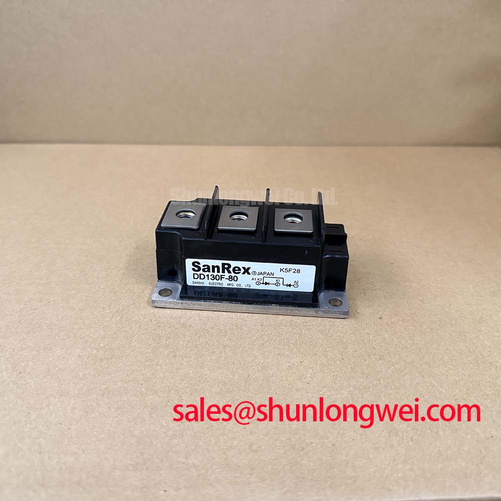
When a repair requires a comparison against another rectifier assembly, SKD82/18 can be reviewed as a separate replacement-evaluation candidate, provided that its voltage class, current capability, mechanical footprint, isolation requirement, thermal interface, and circuit connection are verified against the original design. It should not be assumed to be a direct interchange solely from product category.
Preventing Spurious Faults: Commutation Turn-Off Voltage Control for MP502-BP
Observe the AC terminals and DC rails with appropriately rated differential measurement equipment during controlled switching events. A distorted output waveform, unexpected AC-side ringing, or unstable DC-link behaviour may involve wiring inductance, transformer leakage, capacitor condition, load commutation, or the surrounding switching stage. The supplied official specifications do not provide reverse-recovery current, reverse-recovery time, or soft-recovery classification for the MP502-BP; these values should therefore not be assigned to this module without manufacturer documentation.
Engineering Recommendation: minimize the high-current commutation-loop area where practical, especially between the bridge, DC-link capacitors, and switching load, to reduce inductive voltage overshoot during current transfer. The required layout, suppression network, and test limits remain system-determined and should be validated against the actual DC-link voltage and measured transient waveform.
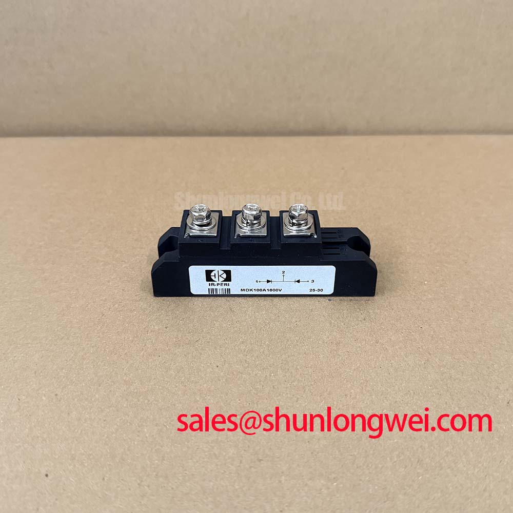
In equipment where a separate upstream or auxiliary rectifier is present, the SKD 25/14 may be evaluated as another topology-level component. Its use must be confirmed from its own ratings and the original schematic, rather than inferred from the MP502-BP connection arrangement.
MP502-BP Thermal-Electrical Optimization: Short-Circuit Withstand Coordination
For a suspected downstream short circuit, isolate the load before replacing the bridge and test the AC source, DC-link capacitors, wiring harness, load stage, and protective devices separately. The 400A 8.3 ms half-sine IFSM rating defines a limited surge condition, not a guaranteed clearing capability for every dead-short event. Fault current magnitude and duration depend on the source transformer, line impedance, conductor resistance, fuse response, and fault location.
Design Consideration: protection coordination should aim to interrupt abnormal current before cumulative semiconductor stress becomes unacceptable. The system engineer should obtain the actual semiconductor-fuse time-current and I²t documentation, then validate the coordinated fault path through controlled analysis and safe test methods. Do not claim zero-damage behaviour without documented protection coordination and equipment-level verification.
For broader discussion of switching-device technology choices and system-level design tradeoffs, see the Wide Bandgap Revolution engineering guide. Such technology comparisons do not change the official 200V, 50A, 2500V AC isolation, or temperature ratings of the MP502-BP bridge rectifier module.