

Content last revised on September 18, 2026
Field Diagnostics & Commissioning: Cosmic Ray Robustness and Voltage Derating in MPKB2CA150U60 Topologies
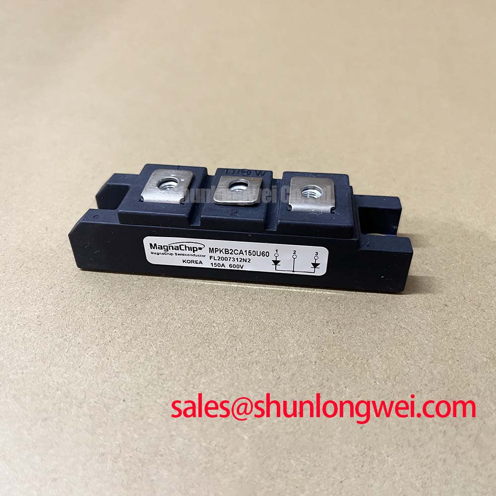
Before installation, isolate the DC link and verify that the cabinet documentation identifies MPKB2CA150U60 as the intended Mitsubishi Electric power module; then inspect terminals, mounting faces, insulation barriers, and mating busbars for contamination, distortion, or loose hardware. The available official ratings identify a 600 V repetitive peak reverse-voltage rating, 150 A average forward current, ultra-fast reverse recovery behavior, a typical 1.4 V to 1.8 V forward-voltage drop, and 2500 V AC isolation voltage. These values should be treated as Official Datasheet Specifications for this model’s published rectification-related electrical boundary, not as system-level performance guarantees.
| Official Specification | Rated Value | Integration Relevance |
|---|---|---|
| Repetitive Peak Reverse Voltage, Vrrm | 600 V | Defines the published reverse-voltage boundary for rectification duty. |
| Average Forward Current, If_avg | 150 A | Defines the published average forward-current rating. |
| Reverse Recovery Time, trr | Ultra-Fast | Relevant when evaluating switching-related recovery behavior in PWM power stages. |
| Forward Voltage Drop, Vf | 1.4 V to 1.8 V typical | Supports conduction-loss assessment at the applicable operating condition. |
| Isolation Voltage, Visol | 2500 V AC | Separates the power-side structure from the mounting and control environment within the specified test context. |
During commissioning, begin with the measurable electrical boundary: confirm the DC-link waveform, expected reverse-voltage polarity, current path, and isolation arrangement against the original equipment schematic. The 600 V Vrrm rating is an Official Datasheet Specification, while the actual peak voltage at the module is determined by the complete circuit, including supply transients, commutation current, wiring inductance, capacitor placement, and connected load behavior. An oscilloscope measurement using an appropriate high-voltage differential probe is the practical way to verify that operating peaks remain within the system design limit.
Cosmic-ray and terrestrial-neutron exposure, including elevated-altitude operation, should be treated as a Design Consideration rather than a published robustness claim for this model. No FIT rate, single-event burnout threshold, altitude derating curve, or lifetime prediction is established by the supplied official parameter set. Engineers maintaining electric material-handling equipment should therefore review the OEM’s environmental qualification requirements and evaluate the complete converter at its intended DC-bus voltage, temperature, enclosure condition, and operating location.
Where intermittent failures appear after commissioning, inspect the evidence rather than assigning one cause. Capture switching events, compare them with a known-good signal path where available, check DC-link connections and insulation clearances, and examine whether the event correlates with regenerative braking, cable movement, temperature, or supply disturbances. For topology context, the operating principles behind an industrial boost converter can help technicians map stored-energy and commutation paths before deciding which nodes require measurement.
Preventing Spurious Faults: Symmetrical Busbar Geometry for High-Current Guidelines for MPKB2CA150U60
The 150 A If_avg rating supports evaluation of substantial forward current, but it does not establish current sharing, gate-drive behavior, VCE(sat), or a transistor temperature coefficient for this specific part. Those characteristics are not included in the provided official data and should not be inferred from the product category. When the module is integrated into a larger power assembly, busbar geometry should keep the outgoing and return paths physically coupled and as symmetrical as the assembly allows. This Design Consideration reduces loop area, which helps limit inductive disturbance during current transitions.
For a repair installation, clean the mating surfaces, remove only residues compatible with the original assembly process, and check that the module sits flat before final fastening. Thermal-interface thickness, clamp hardware, Belleville washer arrangement, and tightening torque must be taken from the original equipment or mounting documentation. A thin, continuous thermal interface is generally preferred to avoid air gaps, but its final thickness and compression must be validated for the specific heatsink flatness, hardware, and mechanical stack.
Field Alert: De-energize the equipment and confirm that stored DC-link energy has been discharged before loosening any power connection or mounting hardware.
For assemblies using controlled semiconductor switches near this module, keep the command and return conductors paired and avoid routing sensitive control wiring alongside high-current commutation paths. Gate-loop damping, Miller-effect suppression, active clamping, and driver supply selection are Engineering Recommendations that must be developed from the actual switching-device datasheet and verified by system testing; they are not official specifications of MPKB2CA150U60.
Preventing Spurious Faults: DC-Link Capacitance Bank Layout and Low-ESR Evaluation for MPKB2CA150U60
Place the DC-link capacitor bank so the high-frequency commutation route between the capacitor, power module, and return conductor is compact. The engineering relationship between peak voltage, DC-link voltage, loop inductance, and current-transition rate explains why a long or asymmetric connection can produce an overshoot even when the nominal bus voltage appears acceptable. The required capacitor technology, capacitance value, snubber arrangement, ESR, and allowable parasitic inductance are system-determined values; select and verify them from measured current waveforms, switching frequency, thermal conditions, and the equipment manufacturer’s design documentation.
MPKB2CA150U60 is published with ultra-fast reverse recovery. This Official Datasheet Specification is relevant to PWM commutation analysis, but it does not substitute for measuring the completed assembly. A ringing waveform may reflect busbar geometry, capacitor connection length, probe grounding method, contact resistance, or the behavior of other power devices in the circuit. Inspect all of these contributors before changing parts or adding suppression components.
In forklift low-voltage traction equipment, cabling between battery, contactor, inverter, and auxiliary power sections can change the observed transient environment. Engineers should measure at the module terminals and at the capacitor bank, using a test arrangement that does not introduce a misleading measurement loop. The article Resonant Topologies in Home Appliances provides useful context on how topology and commutation paths affect switching stress, although final suitability must be established against the traction system’s own electrical conditions.
MPKB2CA150U60 Operational Boundaries: Evaluating Braking Resistors and Chopper Transistor Limits
Regenerative motor deceleration can raise DC-link energy, making the braking resistor, chopper transistor, control threshold, capacitor bank, and protective logic a coordinated system function. The supplied specifications for MPKB2CA150U60 do not define a braking-resistor wattage, pulse-energy capacity, chopper-transistor rating, gate-drive threshold, or allowable regenerative duty cycle. These values must be established from vehicle mass, speed profile, motor behavior, DC-link capacitance, battery acceptance, enclosure thermal conditions, and the original controller design.
For field troubleshooting, identify whether the issue occurs during acceleration, steady travel, lift operation, or deceleration. Record DC-link behavior and braking command activity, then check resistor connections, thermal protection paths, contactor behavior, and relevant controller fault records. A braking-related fault can arise from several interacting conditions, so replacing the module without waveform and connection checks can leave the original system issue unresolved.
When an engineering team is assessing a different power-module family for a repair or redesign, CM100DY-12E is a separate Mitsubishi Electric module that can be reviewed as a neutral comparison point. Its electrical ratings, package arrangement, terminal layout, thermal interface, control requirements, and protection coordination must be checked independently against the original equipment documentation before any substitution decision.