


Content last revised on September 30, 2026
Field Diagnostics & Commissioning: Evaluating Post-Surge Reverse Voltage Block in MTC400A-1800V Topologies
| Parameter | Specification |
|---|---|
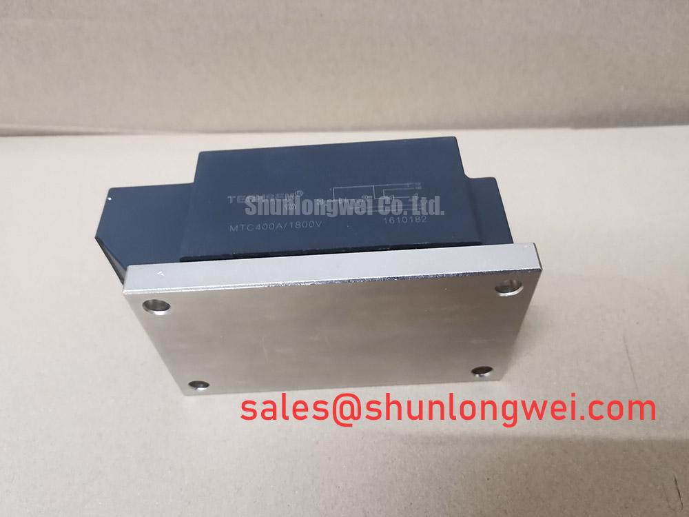
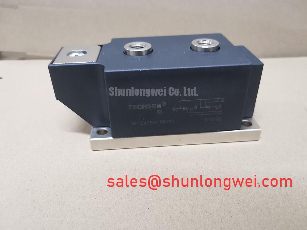
| Model | MTC400A-1800V |
| Manufacturer | SanRex (Sansha Electric) |
| Product category | Thyristor / Diode Module |
| Working voltage | Standard Industrial Rating |
| Rated current | Standard Operating Current |
| Package | SanRex Power Module |
Isolate the power stage, discharge the DC link, and record cold-state resistance and diode-direction readings between every accessible main terminal before applying reverse voltage again. Compare those readings with a known-good unit or the original equipment baseline rather than treating one multimeter result as a complete health diagnosis.
For a medium-frequency induction melting and hardening furnace, inspect the rectifier and controlled-conversion path for visible terminal discoloration, loosened hardware, cracked insulation, and evidence of thermal stress. The MTC400A-1800V is identified as a SanRex power module in the supplied product data, with a standard industrial working-voltage rating and standard operating-current designation. The precise surge-current, repetitive reverse-voltage, junction-temperature, and fuse I2t values must come from the applicable manufacturer documentation for the exact production variant.
During commissioning, verify terminal identity against the original wiring diagram, then check that the semiconductor polarity agrees with the intended current path. A reverse-voltage event should be investigated alongside fuse operation, contactor timing, transformer leakage, and commutation conditions. Reapply voltage only after the measured insulation condition, cooling path, and protective coordination have been reviewed.
🔧 Bench Diagnostic: Use ESD protection and keep the module disconnected from parallel capacitors before taking cold-state diode and resistance measurements.
MTC400A-1800V Thermal-Electrical Optimization: RC Snubber Network Optimization for Practical Tuning
Probe the switching node and gate or control timing with the furnace isolated from its normal load, then compare overshoot and ringing against the known-good waveform before changing the snubber network. This separates a commutation disturbance from a wiring, trigger, or load fault.
An RC snubber can reduce unwanted voltage transients, while a series saturable reactor may moderate the initial current slope in a high-power induction-converter topology. These are design considerations, not factory parameters of the MTC400A-1800V. The resistor and capacitor values must be selected from measured switching waveforms, repetitive peak voltage, pulse energy, thermal dissipation, and the actual furnace impedance. Designers should verify the result at the intended firing pattern and load range.
Minimize the physical loop area between the module, snubber, and commutation path to reduce parasitic inductive overshoot. Confirm that the snubber capacitor has a suitable impulse and repetitive-voltage rating, and that the resistor can dissipate the resulting pulse energy without changing value during operation. The system engineer should validate peak voltage against the module’s applicable reverse-voltage limit and confirm that the protective fuse remains coordinated with the modified transient behavior.
Where a rectifier stage feeds the converter, the related FRS300CA50 may be reviewed as a separate complementary topology reference. It should not be treated as an automatic substitute for the SanRex module.
Field Diagnostics & Commissioning: AC-to-DC Transfer Characteristics in MTC400A-1800V Topologies
Capture the line voltage, module current, and firing command simultaneously while stepping through the operating command range, beginning with a current-limited test condition. A distorted current waveform, delayed conduction, or unequal phase loading requires comparison across all relevant branches rather than a single terminal reading.
In a controlled rectifier used for induction heating, the AC-to-DC transfer characteristic depends on firing angle, source impedance, load power factor, commutation overlap, and control synchronization. The test range from zero degrees to one hundred and fifty degrees is an application test condition, not an official electrical limit supplied for this product. Engineers should calculate the expected average output and reactive-power demand from the complete converter topology, then verify the result with measured RMS current and line displacement.
Check that the trigger signals reach the intended terminals with consistent timing and adequate isolation. Inspect the current-sharing path where multiple devices operate in parallel, because unequal wiring resistance, thermal gradients, or trigger mismatch can cause one branch to conduct more heavily. Any parallel arrangement requires static and dynamic current-sharing validation at the actual operating temperature.
For comparative component research, the CVM75BB160 can be reviewed as a separate SanRex-related power-module listing. Selection must remain based on terminal arrangement, electrical ratings, cooling method, and the original equipment documentation.
Preventing Spurious Faults: Reverse Recovery Charge Guidelines for MTC400A-1800V
Use an oscilloscope with suitable differential and current probes to observe commutation current, reverse-recovery behavior, and voltage rise at the module terminals under the real transformer and load conditions. Compare the waveform with the protective fuse response and the control timing before assigning the disturbance to the module itself.
Reverse-recovery charge, peak recovery current, recovery time, junction temperature, stray inductance, and switching frequency all influence commutation loss and electromagnetic interference. The supplied product information does not provide numerical values for Irrm, trr, recovery softness, or fuse I2t coordination. Those figures must therefore be taken from the exact SanRex technical documentation applicable to the module variant.
Keep the commutation path compact, confirm symmetrical terminal connections, and verify that the snubber and fuse operate within their documented pulse and voltage limits. The general diode recovery mechanism is outlined in the flyback diode reference, while the Mitsubishi Electric diode module lineup provides useful industry context for comparing module functions.
For practical inspection methods covering failure analysis, terminal checks, and installation discipline, consult the Field Engineer’s Handbook. Final acceptance should be based on measured insulation, thermal behavior, waveform margins, and the original equipment manufacturer’s protection requirements.