

Content last revised on September 10, 2026
Suppressing Localized Thermal Gradients to Prevent Chronic Optical Yellowing and Color Shift
Inspect the cabinet airflow path before fitting the panel. A display module can be exposed to heat from power supplies, processor boards, communication equipment, or restricted ventilation, even when the surrounding cabinet temperature appears acceptable. The NL10276BC30-32D product context confirms the module type, but it does not provide a verified thermal map, backlight construction, optical material specification, L70 value, or B50 value. Those characteristics should not be treated as model specific without the applicable NEC documentation.
As a Design Consideration, a mechanical integrator may evaluate aluminum spreader rails or an equivalent external heat spreading method along narrow display edges when measurements show a localized temperature gradient. The purpose is to distribute heat and reduce local stress on the display assembly, not to assume a particular internal optical material or guaranteed color life. Rail placement should be checked against the bezel, active area, cable routing, and rear clearance. The display frame must remain evenly supported so that thermal expansion does not introduce concentrated pressure into the panel.
For a SCADA dispatch console, measure the temperature at the panel perimeter, behind the module, and near nearby heat sources during a representative operating cycle. Compare the readings with the environmental limits stated in the original panel documentation. If color changes appear after thermal exposure, inspect the backlight drive, power rail stability, enclosure airflow, and surface contamination as separate variables. A visible shift is not sufficient evidence of one specific internal failure mechanism.
Signal integrity also deserves a direct bench check. The available product data does not confirm whether this exact module uses TTL, LVDS, or another interface arrangement, nor does it define transmitter clock jitter margins or data hold times. The system integrator should verify the interface from the original wiring diagram and panel datasheet. If a differential link is used, route the pair consistently, control return current, and keep noisy switching nodes away from the display cable. Any impedance target, termination arrangement, clock margin, and hold time must be derived from the confirmed interface specification and validated with an oscilloscope across the intended temperature range.
Full Screen Primary Color AOI Screening for Stuck Sub Pixels and Background Uniformity
Run the replacement evaluation with full screen red, green, blue, white, black, and neutral gray test patterns. This gives the maintenance team a practical way to inspect stuck sub pixels, uneven luminance, visible shadowing, and contamination without assigning an unsupported fault code to a single symptom. Record the result at controlled brightness and from the normal operator viewing position. The factory information supplied for NL10276BC30-32D does not state pixel count, luminance, contrast, viewing angle, or uniformity limits, so acceptance criteria should come from the equipment service manual or the applicable NEC panel documentation.
A three stage bench sequence is useful. First, check the unpowered front surface and frame for scratches, pressure marks, loose trim, and cable strain. Second, display the primary color fields and inspect the complete active area for persistent dots, lines, or regional shading. Third, display a dark field and use a flashlight held at approximately 45 degrees as a Design Consideration for locating surface shadows, bezel reflections, or areas where the backlight contribution differs. This optical check can help separate a visible backlight pattern from a signal path defect, but it cannot independently prove a COG driver fracture or any other internal cause.
When a line or region changes with the video pattern, compare the source signal with a known good path. If the interface is LVDS, verify pair continuity, connector seating, shield termination, and clock activity according to the confirmed pinout. If the interface is TTL, check the documented logic levels and timing instead of applying a generic voltage assumption. The system integrator should verify the required supply voltage from the original panel documentation.
Automatic optical inspection can be used for repeatability, but the camera exposure, viewing angle, and test pattern must remain consistent. A dark corner may result from optical geometry, mechanical compression, backlight behavior, or a display drive issue. Use comparative evidence from the same equipment model and inspect the panel after thermal stabilization before making a replacement decision.
Dynamic Contrast Ratio Stabilization and Liquid Crystal Birefringence Temperature Tracking
Contrast and gray scale behavior should be evaluated with the display installed in its intended bezel, because ambient reflection and viewing position can alter the operator’s perception. The supplied factory context does not confirm whether the NL10276BC30-32D uses TN, IPS, MVA, or another liquid crystal mode. It also does not verify a symmetric 85 degree viewing cone, anti glare etching, anti reflection treatment, or a specified gray to gray response time. These properties require confirmation from the original technical documentation rather than inference from the model number.
For a substation protection or SCADA console, compare black, white, and intermediate gray patterns at the normal eye position and at the practical operator viewing range. Watch for gray inversion, loss of shadow detail, glare from overhead lighting, and changes caused by the enclosure window. If the display has an anti glare or anti reflection surface, clean it only with a method approved for the panel finish. Abrasive materials and unsuitable solvents can permanently change surface appearance.
Temperature tracking should be performed during a controlled cold start and warm operating period when the equipment specification permits those conditions. Liquid crystal viscosity generally changes with temperature, which can influence response behavior, but the magnitude and acceptable limit are model specific. If gray to gray transitions appear slower at low temperature, verify the panel temperature, image source timing, backlight behavior, and controller configuration before attributing the observation to the liquid crystal layer.
A heater strip or enclosure heater may be considered only when the complete system design requires it and the panel documentation permits the approach. Its control method, placement, insulation, and thermal cutout are system responsibilities. The heater must not create a localized hot spot or press against the active area. Dynamic contrast settings should also be evaluated with the actual graphics controller because aggressive image processing can alter perceived gray scale without indicating a panel defect.
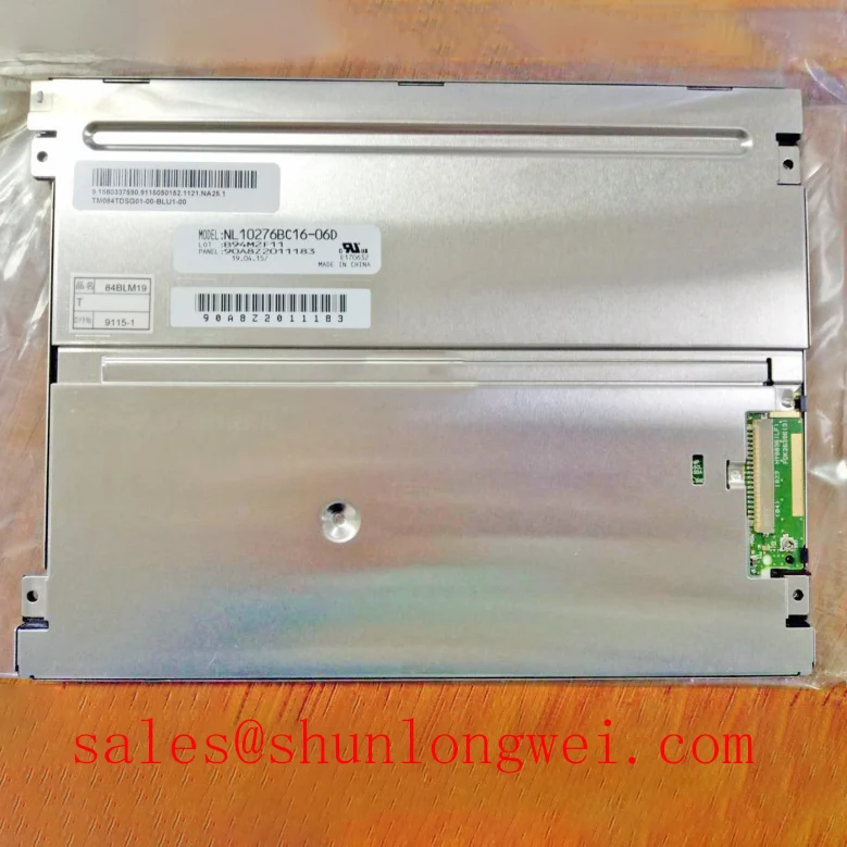
For cross reference work, engineers can review the mechanically related NL10276BC16-06 as a separate candidate, but compatibility must be checked through dimensions, connector assignment, timing, optical characteristics, mounting details, and environmental ratings. A similar product name is not sufficient evidence of interchangeability.
Wide Temperature Operational Margin and Sub Zero Liquid Crystal Viscosity
The requested evaluation window of minus 30 degrees Celsius to plus 85 degrees Celsius must be treated as a test condition to verify, not as an official rating for NL10276BC30-32D. The confirmed information supplied for this product identifies the manufacturer, module category, and TFT LCD construction, but it does not state an operating temperature range, storage range, humidity limit, condensation requirement, or thermal cycling qualification.
When the original documentation confirms a suitable temperature range, assess the display in the complete enclosure rather than on an exposed bench alone. Check the gasket contact around the bezel, the panel seating surface, cable flexibility, rear clearance, and the condition of any vent or filter. Uneven mounting pressure can create optical nonuniformity or mechanical stress, while a damaged seal can allow dust and moisture to reach the display area. Condensation risk is determined by the enclosure, temperature transition, humidity, and cabinet pressure conditions, so the system designer should validate those factors together.
At low temperature, allow the assembly to stabilize before judging response time or gray scale behavior. Capture the same test pattern during cold start and after warm-up, then compare the signal timing and visual response. If a controller uses PWM backlight dimming, the integrator should verify the actual PWM frequency and duty cycle behavior from the panel or backlight documentation. A generic PWM value must not be applied to this model without confirmation, because the backlight driver architecture and acceptable dimming method are not established in the supplied factory data.
Backlight troubleshooting should begin with the documented power path. Inspect the connector, fuse or protection device, enable signal, current regulation, and feedback or fault output where those functions are provided by the system. An open or short condition in the backlight circuit can also be related to the external driver, wiring, or protection circuitry. Measure against a known good assembly and the approved schematic rather than assuming that the LCD module itself contains a particular overvoltage or short circuit protection feature.
Maintenance Note: Inspect the cabinet cooling path and bezel gasket condition during scheduled service, and disconnect power before removing the display cable.
For broader enclosure, sealing, thermal management, and industrial HMI integration guidance, refer to Industrial Display and HMI Solutions. The NL10276BC30-32D should be released for a specific console only after the original electrical interface, mounting geometry, optical requirements, power sequencing, and environmental limits have been checked against the equipment design.