Content last revised on October 20, 2026
Thermal Dissipation and Optical Component Preservation
Thermal inspection around the narrow display edges should begin with the enclosure removed and the panel operating at the same image level used in service. Edge concentration can create visible brightness drift, local colour change, or delayed image response, especially when the display is installed behind a tightly fitted railway console. A chassis heat spreader may be evaluated as a Design Consideration when the enclosure shows a concentrated warm region near the backlight edge. Its dimensions, contact pressure, electrical isolation, and heat path must be determined by the system designer rather than assumed from the panel name.
Do not treat a light guide plate or optical film as a field replaceable component unless the original construction and service procedure confirm that option. Mechanical pressure, contamination, and uneven support can produce dark-field mura or bright bands that resemble LED failure. When low-temperature operation is expected, observe grey-to-grey transitions during a cold-start test. Liquid crystal response can become slower at sub-zero temperatures, so any heater or enclosure temperature control should be assessed as system hardware, not as an assumed accessory of this NEC module. Record the time from power application to stable text rendering and compare it with the equipment service requirement.
Rail vibration also changes the thermal and mechanical picture. Check that the display frame is supported across its intended mounting points without transferring concentrated load into the active area. If an alternative panel is being evaluated, the NL12876AC18-03 should be compared through a dimensional, optical, connector, and timing review rather than treated as an automatic substitute.
Display Interface Synchronization and Logic Power Rail Verification
Begin interface verification at the host board and work toward the panel connector, confirming the signal naming, connector orientation, logic supply, clock relationship, and colour mapping against the original documentation. The available product identity confirms an active matrix TFT colour module, but it does not by itself confirm whether the installed system uses TTL RGB, LVDS, or another signalling arrangement. The system integrator should verify the required supply voltage and interface type from the original panel documentation before applying power.
For a system documented as a 24 bit TTL RGB interface, inspect the red, green, blue, pixel clock, data enable, and synchronisation signals as one timing group. A split image, incorrect colour order, or unstable text can result from mapping differences, connector orientation, timing incompatibility, or a power sequencing problem. JEIDA and VESA naming should be treated as board-level configuration references only after the actual transmitter and receiver documentation has been matched.
The suggested power-on window of 0.5 ms to 10 ms may be used only as a Typical Starting Point when the equipment designer is defining a controlled sequence; it is not an official specification for this model. Measure the supply rise and reset behaviour at the panel connector with the cable installed. For high-speed differential routing elsewhere in the assembly, controlled impedance is a Design Consideration. The routing stack-up, termination, connector geometry, and cable construction determine the final value and require signal integrity verification.
When PWM dimming is present in the host design, a starting evaluation range of 200 Hz to 1 kHz can help engineers check visible flicker, acoustic interaction, and duty-cycle linearity. This is an integration recommendation, not a confirmed feature of the NL10276BC30-34BD. The actual backlight control method must be established from the panel and driver documentation.
Polarizer and Optical Film Inspection under Direct Industrial Lighting
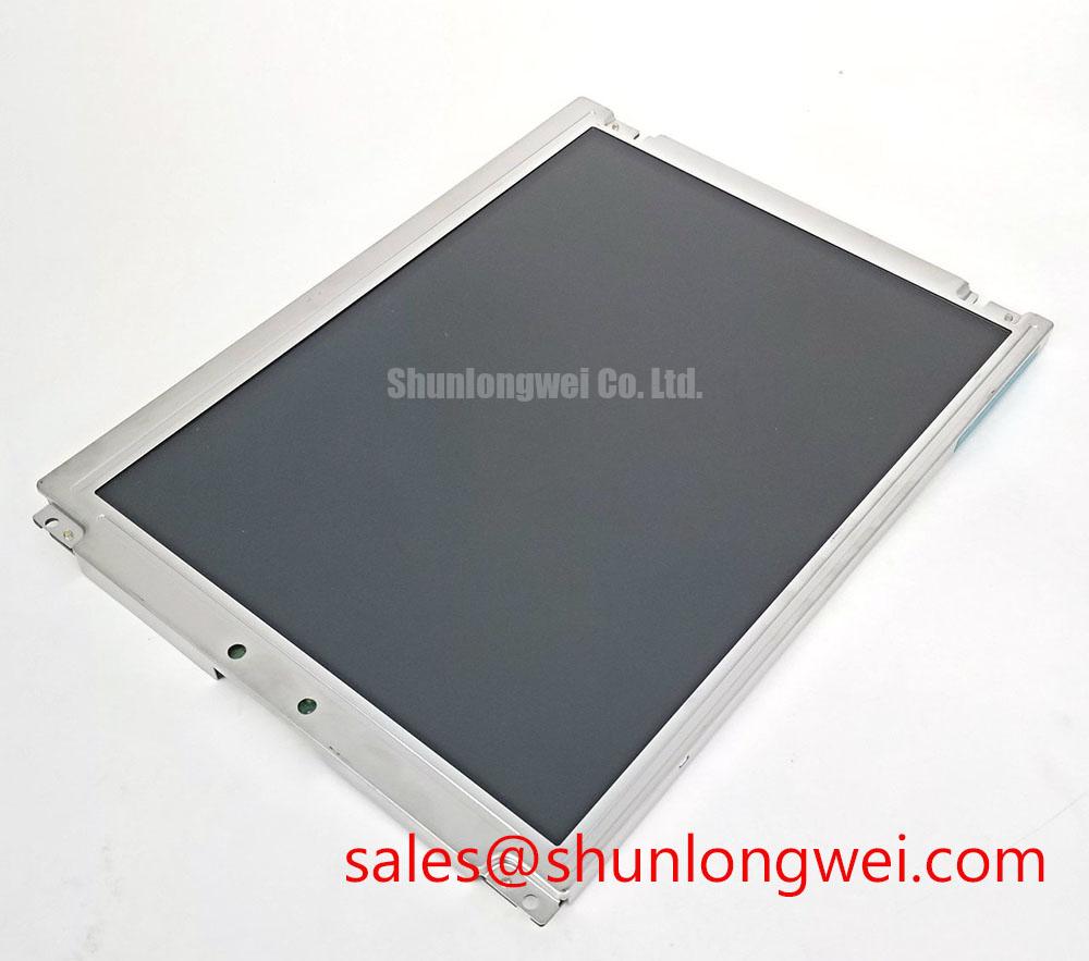
Inspect the polarizer surface under diffuse and direct industrial lighting before accepting the panel into a cab display or passenger information enclosure. Look for scratches, pressure marks, edge lifting, contamination, and nonuniform reflections while displaying a neutral grey field. A clean optical surface can still show viewing-angle colour changes if the installed panel technology and optical stack differ from the original unit, so comparison should be made from the actual operator viewing position.
TN, IPS, and MVA descriptions should not be assigned to this model without a supporting datasheet. In general optical evaluation, TN panels may show grayscale inversion from certain viewing directions, while panels with wider symmetric viewing behaviour are assessed for colour and contrast consistency around the complete viewing cone. The often-used 85°/85°/85°/85° viewing-angle notation should only be recorded when it appears in the verified panel specification.
Surface anti-glare performance is best checked with the display mounted behind its real cover glass or window. Direct sunlight, cab lighting, and overhead industrial luminaires can expose haze, reflections, or surface nonuniformity that is not visible on a laboratory bench. Avoid pressing the active area during cleaning or connector work. A full-colour pixel test followed by a low-level grey sweep helps separate isolated pixel defects from broad optical nonuniformity.
💡 Bench Tip: Use ESD protection and keep the flexible cable perfectly square to the connector before closing its lock, because an uneven insertion can create intermittent colour or row faults without leaving visible damage.
Industrial Bezel Mechanical Envelope Tolerances and Mounting Screw Torque Optimization
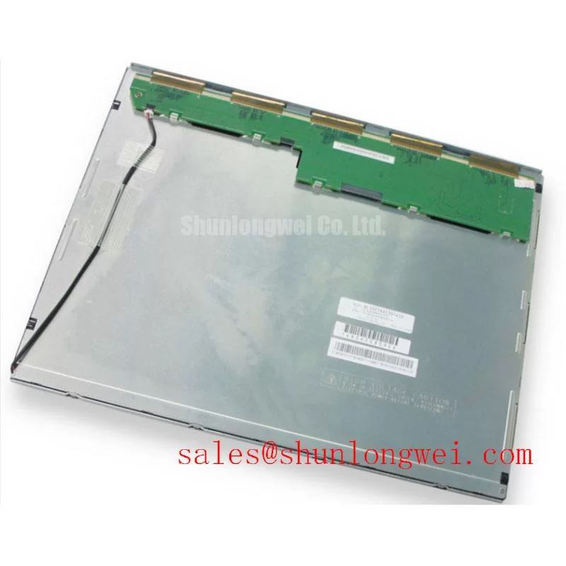
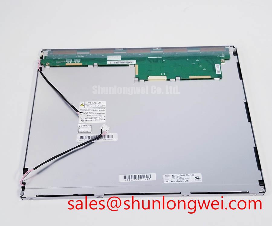
Measure the replacement panel against the original bezel opening before connecting the cable. Confirm active-area position, frame clearance, connector access, screw-hole alignment, rear component clearance, and the path taken by the flexible cable. A standard form factor does not prove identical mechanical dimensions, so the enclosure drawing remains the controlling reference for a railway console or PIS terminal.
Fasteners should be tightened progressively in a cross pattern so the frame seats evenly. The suggested 0.35 N·m to 0.45 N·m range is a general Design Consideration for suitable M3 hardware, not a confirmed NEC factory requirement for this model. The final torque depends on screw grade, insert material, bracket stiffness, washer selection, and the enclosure manufacturer’s specification. Examine the display on a black field after assembly; pressure-related mura may appear only after the bezel is fully secured.
Vibration and thermal cycling can change cable strain at the connector. Provide a smooth cable path without sharp folding, and ensure that the locking mechanism remains accessible for inspection. If the host uses TTL or LVDS transmission, evaluate clock stability and data hold behaviour at the actual operating temperature range. Oscilloscope comparison at the panel connector is more useful than relying on a nominal interface label, particularly when the original equipment has long cables or multiple interconnects.
For broader installation practices covering industrial TFT selection, optical inspection, and system integration, consult The Ultimate Guide to Industrial TFT LCD Technology. The NEC NL10276BC30-34BD remains suitable for evaluation where its verified mechanical, electrical, optical, and interface requirements match the existing equipment documentation.