Content last revised on September 22, 2026
Preventing Localized Light Guide Plate Compression Warp on Dark Screen Fields
Before fitting the NL160120BC27-10, inspect the TFT-LCD module perimeter, viewing surface, mounting points, and interface area under clean bench lighting, then compare the replacement unit against the original equipment documentation before power is applied.
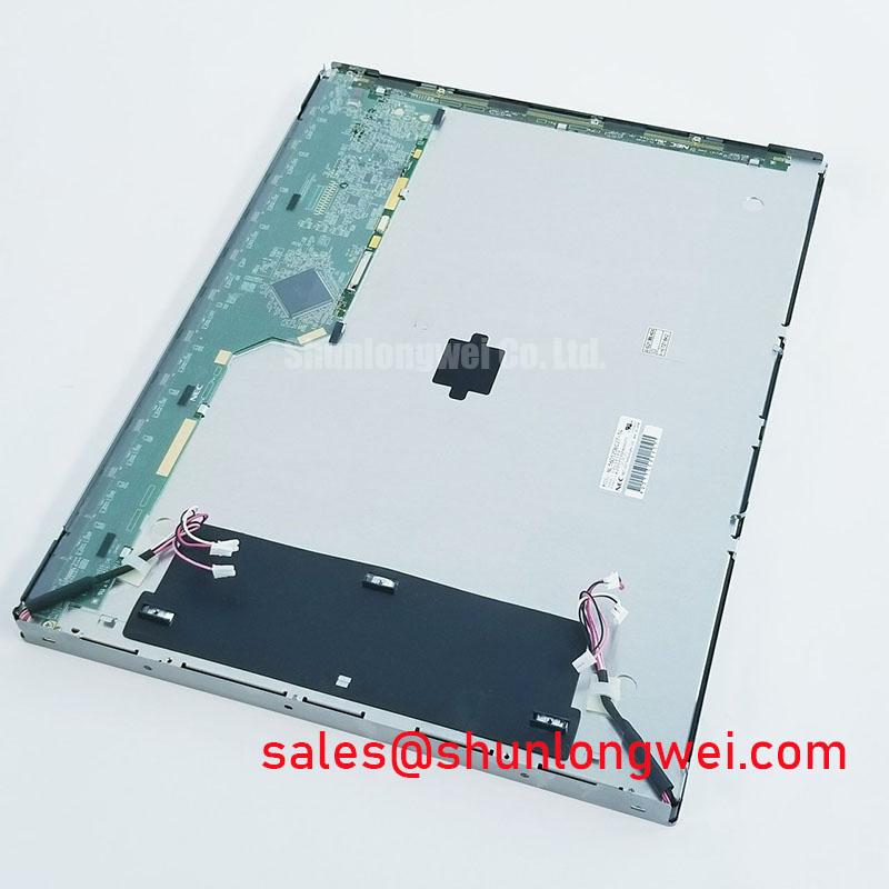
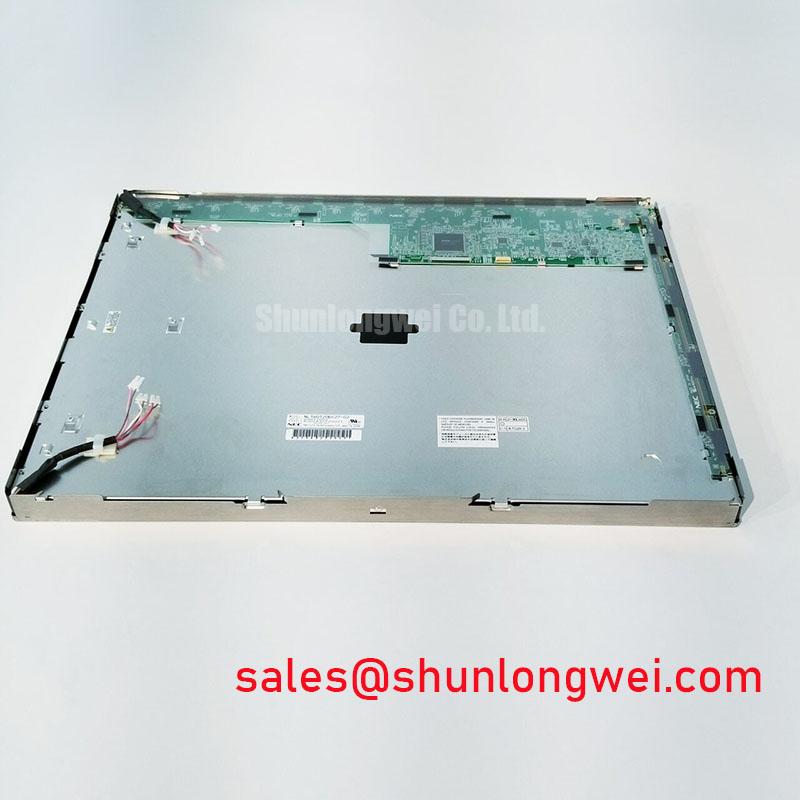
The NL160120BC27-10 is an NEC TFT-LCD Display Module. Available product information identifies the manufacturer, model, and module type, while electrical input requirements, interface assignment, optical figures, mechanical drawing dimensions, environmental limits, and backlight details must be confirmed from the original panel documentation and the host equipment service data.
| Item | Available Information |
|---|---|
| Model | NL160120BC27-10 |
| Manufacturer | NEC |
| Product Category | TFT-LCD display module |
| Module Type | TFT-LCD Display Module |
| Specification Status | Detailed specifications require confirmation from the original product documentation |
Start the mechanical assessment with the inactive display surface. A dark image field is useful because local pressure effects, uneven panel support, contamination behind a front window, and bezel distortion can become easier to see than they are on a bright operating screen. Inspect the equipment bezel for burrs, warped standoffs, hardened sealing material, trapped harness sections, and any point where the enclosure transfers force directly onto the visible area of the LCD module.
The official information available for the NL160120BC27-10 identifies it as a TFT-LCD module, but does not provide a confirmed chassis envelope tolerance, fastening pattern, fastener size, torque value, light-guide construction, contrast ratio, anti-glare specification, or sunlight readability figure. These items should not be transferred from another NEC panel, even where the physical appearance seems similar. A panel that fits inside the same opening can still have different mounting lands, support requirements, optical stack thickness, or connector placement.
Design Consideration: a mounting frame should support the module through its intended mechanical features rather than compressing the active display area. During reassembly, engineers should check that the panel sits flat before tightening fasteners, and that enclosure covers do not bend the module after final closure. An uneven bezel load can present as patchy brightness, dark-field nonuniformity, or apparent mura, yet the visible symptom alone does not establish the root cause. Compare the image with the module temporarily installed in a relaxed, nonbinding condition where service procedures permit.
The requested application may involve telematics displays in heavy earthmoving or mining equipment, where vibration exposure and dirt ingress are legitimate compatibility concerns. That use case should be treated as an equipment-level evaluation rather than a declared rating of this panel. The system integrator should verify the enclosure sealing strategy, vibration retention method, display window clearance, and temperature management against the original machine documentation.
⚠️ Maintenance Note: Inspect cooling paths, front-window seals, and mounting pads during scheduled service because hardened or displaced materials can introduce uneven mechanical stress across a display assembly.
For a replacement evaluation, record the original panel’s visible image position, bezel contact locations, mounting sequence, and any spacer arrangement before removal. These observations often matter more than applying a generic fastening value. If a service drawing calls for a cross-pattern sequence or a defined torque, follow that equipment-specific instruction. Where no approved instruction is available, do not infer an M3 torque limit from unrelated display assemblies; establish the retention method through controlled fit verification and responsible system-level testing.
Suppressing Pixel Jitter and Horizontal White Lines Induced by Adjacent 400V Motor Drives
When intermittent pixel movement, horizontal white bands, image tearing, or a temporary loss of stable video appears near motor-drive operation, inspect the complete signal path before attributing the issue to the display. Check connector seating, cable strain relief, shield termination continuity, display grounding references, drive-cabinet bonding, and the routing relationship between the display harness and high-energy motor wiring. A disturbance can enter through the video path, power distribution, enclosure coupling, or a shared return path.
The NL160120BC27-10 should be connected only after its required interface type, supply rails, pin allocation, and power sequencing have been verified from the original panel documentation. The confirmed product information does not identify an LVDS interface, TTL interface, clock tolerance, data hold time, transmitter requirement, or cable specification. It would therefore be inaccurate to prescribe a differential impedance target, a skew allowance, or an interface-level jitter margin as an official characteristic of this exact NEC model.
Design Consideration: where the host equipment documentation confirms a shielded high-speed display connection, cable shielding should be terminated in a manner compatible with the equipment’s grounding architecture. The objective is to reduce coupled noise while avoiding an unreviewed change to the return-current path. Common-mode suppression components can be assessed at the system level when measured noise indicates a cable-borne disturbance, but component selection and placement should be validated against signal integrity measurements on the known-good interface.
A useful troubleshooting sequence begins with the machine stationary and the display operating from a verified supply condition. Observe the image, then compare behavior while nearby motor drives are inactive and active. If the symptom changes with cable movement, inspect mechanical strain and connector contact first. If it changes with drive switching activity, review cable routing and bonding continuity, then use an oscilloscope with appropriate probing practice to compare the signal path against a known-good installation. Pixel jitter may indicate noise coupling or timing instability, but it may also arise from host-controller behavior, supply disturbance, loose interconnects, or a damaged cable.
Do not route a display cable alongside motor output conductors merely because the route is convenient. Engineering Recommendation: separate sensitive display wiring from high-energy paths where the cabinet architecture permits, maintain orderly service loops, and verify the final arrangement while the equipment is operating under representative conditions. The panel itself is only one part of the display chain; the controller board, cable assembly, power source, chassis bonding, and installation geometry all affect image stability.
For broader service guidance on fault isolation, enclosure management, and HMI integration practices, consult Industrial Display & HMI Solutions. That resource is relevant when evaluating the system around the module without assigning unverified EMC performance or compliance claims to the individual TFT-LCD panel.
Surface Anti-Glare and Anti-Reflective Coating for High Ambient Readability
Assess readability with the original machine display window, not with the bare module alone. A panel can appear acceptable on a workbench yet become difficult to read after it is placed behind a scratched cover lens, a reflective protective window, or an enclosure that admits direct ambient light. Clean the viewing surface using a method approved for the equipment, inspect the cover for haze and residue, and compare the image with the original assembly under the expected viewing angle.
The available official information for the NL160120BC27-10 does not confirm anti-glare treatment, anti-reflective treatment, contrast ratio, luminance, viewing angle, display mode, optical compensation behavior, or a specified high-ambient illumination result. It also does not confirm whether the optical architecture should be described as TN, IPS, MVA, or another TFT implementation. Those terms should not be applied to this model without the manufacturer’s optical documentation.
Design Consideration: anti-glare surfaces can reduce objectionable reflections by diffusing incident light, while anti-reflective treatments are generally evaluated by their effect on surface reflection. Either approach involves system tradeoffs that include perceived sharpness, cleaning requirements, cover-lens interaction, and readability from the actual operator position. If the host equipment needs a cover lens or touch overlay, its optical and mechanical effect should be evaluated as part of the complete HMI stack.
Changes in grayscale appearance across viewing angle do not automatically prove a panel defect. They can be related to the display technology, the selected viewing direction, host timing, controller gamma settings, temperature, polarizer condition, or the angle imposed by the physical installation. A service technician should first compare the suspect unit with the original panel under the same host controller, cable, image source, and viewing geometry. If a known-good panel is unavailable, use stable test images containing black, white, gray, color fields, and fine lines to document what changes as the viewing angle changes.
Backlight condition also deserves separate attention. The official information provided for this model does not state a backlight type, brightness-retention curve, LED life figure, operating current, or constant-current driver requirement. Avoid applying generic claims such as a particular half-brightness hour value to this exact module. Instead, inspect the host backlight supply and any controller-reported fault status according to the equipment documentation. Uneven brightness can be associated with the panel, its illumination system, the power source, contamination, mechanical stress, or optical layers in the finished enclosure.
Where a second part number is being assessed during repair planning, NL160120BC27-14 can be reviewed as a potential replacement candidate. Compatibility must still be verified at the documentation level, including interface assignment, mechanical arrangement, optical behavior, and host-controller requirements. A closely related designation is not sufficient evidence of interchangeable electrical or mechanical performance.
Aluminum Heat Spreader Sizing and Thermal Interface Placement along Narrow Display Edges
Inspect the display compartment for localized heat sources before installing the NL160120BC27-10. Pay particular attention to power supplies, controller boards, drive electronics, enclosed harness bundles, and any metal rail that transfers heat into the display frame. Evidence such as discolored sealing material, persistent window haze, unstable brightness, or an image that changes after warm-up should trigger a whole-assembly inspection rather than an immediate conclusion about the LCD module.
The factory information supplied for this NEC TFT-LCD module does not provide thermal resistance values, approved heat-spreader dimensions, thermal-interface material requirements, thermal pad thickness, LED junction limits, L70 or B50 performance data, or permissible edge loading. It is not appropriate to state that a particular aluminum rail, thermal interface, or heat-spreader placement is required for this model. Any thermal hardware around the module must be evaluated against the original equipment mechanical design and the panel documentation.
Design Consideration: where an enclosure has narrow display edges and nearby electronics generate heat, thermal spreading should be arranged so that it does not create point loads, block service access, interfere with the display cable, or conflict with the intended mounting features. The system objective is to limit localized heat accumulation while maintaining a uniform mechanical interface. Engineers should verify temperatures during representative operation and check the displayed image after thermal stabilization, because a change in appearance may originate in the host electronics, the illumination supply, the panel, or the surrounding optical assembly.
Signal routing should be reviewed at the same time as thermal changes. A metal rail, conductive foil, shielding feature, or revised cable clamp can alter the cable’s mechanical path and electrical environment. If the original documentation confirms a differential display interface, preserve the intended pair relationship and connector orientation during service. If it confirms a single-ended interface, preserve the defined signal return arrangement. The required impedance, timing, and shielding details must come from the module and host-controller documentation rather than from a general display-interface rule.
During preventive maintenance, verify that the display harness does not press against heated surfaces, that strain relief remains effective after enclosure closure, and that the panel is not trapped between incompatible thermal pads or stiff gaskets. If a thermal interface material is used by the original machine design, replace it with a material and geometry approved for that assembly. An improvised pad can improve one thermal contact while adding mechanical compression or changing the mounting plane elsewhere.
For equipment such as heavy shovel and earthmoving telematics displays, engineers often evaluate display modules in the context of dust sealing, vibration retention, window optics, and heat from adjacent controls. The NL160120BC27-10 should be evaluated against those equipment-specific conditions using verified documentation, measured installation behavior, and the original HMI electrical architecture.