Content last revised on October 20, 2026
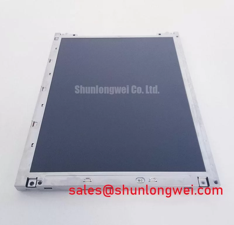
Manufacturer: NEC | Model: NL6448AC33-01 | Class: Industrial TFT-LCD Module | Construction: TFT-LCD Active Matrix Color Display Module | Status: Product Reference
Single Vertical Hairline Defect & Sub-Pixel Column Driver Open-Circuit Localization
When a single vertical hairline appears on a protection relay or SCADA console, I first compare the defect under red, green, blue, white, and black test screens before disturbing the panel frame. A line that remains fixed across primary colors deserves separate treatment from uneven illumination, because the visible symptom can originate in the pixel drive path, the display timing chain, or the optical system.
For the NEC NL6448AC33-01, use a controlled bench source and preserve the original display timing configuration during the comparison. Red, green, and blue fields expose different sub-pixel behavior, while a black field helps separate a continuously driven column artifact from light leakage or backlight nonuniformity. Record whether the line is perfectly straight, changes width with viewing angle, or disappears when the image content changes. These observations provide more useful localization than a single static photograph.
A 45-degree flashlight inspection in a dim environment can add another layer of evidence. Sweep the beam across the front surface while the panel displays a dark field. A shadow that follows the external light source suggests an optical or surface-related effect; a stable narrow line that remains locked to the pixel matrix is more consistent with a display-cell or column-driver path that requires signal-level evaluation. This method does not prove a particular internal failure, but it helps prevent an unnecessary backlight replacement.
Backlight assessment should be performed separately. Compare the affected area with neighboring regions at identical brightness settings and inspect the panel edge for a localized luminance falloff. A regulated backlight driver can sustain visible output even when backlight components or optical layers have aged unevenly. If the backlight is LED and a service program uses an L70 or B50 target, the target must come from the applicable LED or panel reliability documentation rather than being assigned to this NEC model without evidence. A 50,000-hour reference is sometimes used in LED industry studies, but it is not presented here as an official rating for this display.
For a replacement assessment, compare the original connector orientation, active viewing area, mounting envelope, controller timing, and backlight interface. The NL6448BC33-71 may be reviewed as a separate same-family reference, but substitution requires a direct mechanical and electrical comparison rather than a model-number assumption.
Constant Backlight Luminance Output Control & Reliability Verification
Luminance stability begins with the relationship between the panel edge, the backlight driver, and the surrounding chassis. On a narrow industrial display, a metal support rail can conduct heat away from a concentrated region, but its shape, contact pressure, insulation, and enclosure airflow must be evaluated together. The rail should not press directly against an optical layer or create a local bright or dark band.
The NL6448AC33-01 is identified as a TFT-LCD active matrix color display module. Its page-level product information does not establish a universal luminance lifetime curve, L70 value, or B50 value. During qualification, engineers should therefore measure initial luminance and repeat the same measurement at controlled brightness, ambient temperature, and driver current conditions. A service record should distinguish backlight output depreciation from contamination, diffuser aging, optical stress, and controller brightness commands.
Constant-current operation is useful for repeatable evaluation where the backlight is designed for current regulation because it removes one major source of drive variation. It does not remove thermal effects. A heat spreader, enclosure wall, or mounting rail can change the local temperature field, so the display should be checked after thermal stabilization rather than immediately after power-up. Look for gradual edge-to-center drift, localized hot spots, and brightness changes that track enclosure temperature.
Digital timing deserves the same discipline. Where a TTL or LVDS transmitter is used in the host system, verify the actual interface specified by the original panel documentation instead of assuming that a physically similar connector uses the same signaling format. Check clock continuity, data hold behavior, channel alignment, and image stability at the intended operating temperature. Oscilloscope measurements should be taken at the receiving interface with suitable probing, because probe capacitance and long ground leads can make a clean signal appear worse than it is.
Pixel-clock jitter is best considered as a system margin issue. The transmitter, cable, connector, receiver, power integrity, and ground reference all contribute to the timing window. A panel that displays correctly on a short bench cable may show intermittent artifacts after installation inside a metal control cabinet. Route high-speed pairs away from noisy switching nodes, maintain consistent pair geometry, and verify the result using the actual cable and enclosure arrangement.
💡 Pro Tip: Keep each differential pair geometrically consistent through the connector transition and validate clock stability with the display installed in its final enclosure, not only on an open bench.
The linked TCG121XGLPCPNN-AN70 can be considered as a separate display-system reference when reviewing a related controller or optical architecture; it should not be treated as an integrated part of this NEC module.
Thermal Cycling Degradation of Polarizer Adhesives & Sealant Gasket Integrity
Thermal cycling evaluation should begin with the visible optical response at cold start, thermal soak, and return to room temperature. Liquid-crystal viscosity can increase at sub-zero temperatures, which may appear as slower gray-to-gray transitions, temporary smearing, or a change in perceived contrast. These effects should be logged against the panel temperature and image sequence rather than judged from a single frame.
The frequently cited industrial range of −30°C to +85°C is not an official operating rating established here for the NL6448AC33-01. Any qualification plan using that range must be checked against the applicable NEC documentation, the host electronics, and the enclosure materials. The panel should be allowed to stabilize at each condition before judging response time, contrast, or image uniformity.
Thermal expansion mismatch can stress perimeter adhesives, polarizer interfaces, frame joints, and gasket contact surfaces. During inspection, look for edge lifting, haze, localized Newton-ring-like patterns, sealant discoloration, or a defect that changes after the module returns to ambient temperature. These signs are diagnostic clues, not proof of one specific adhesive failure mechanism. Photographing the same edge locations after each cycle makes the progression easier to compare.
Direct sunlight introduces both optical and thermal variables. A contrast ratio above 500:1 at 50,000 lux should be treated as a project acceptance target only when it is defined by the system specification or a verified panel datasheet; it is not stated here as a factory rating for this model. The test should record viewing angle, ambient spectrum, front-cover reflection, brightness command, and measurement geometry. Anti-glare treatment can reduce reflected images, but its effectiveness depends on the cover window, surface finish, and installation angle.
The Tianma industrial display solutions reference is useful for understanding industrial display considerations at the product-family level, while model-specific limits remain the controlling evidence for an actual replacement decision. For field repair, keep the original seal compression pattern and avoid dragging tools across the polarizer surface during frame removal.
Flush-Mount Open-Frame Bezel Integration & Perimeter Gasket Shock Isolation
Flush mounting should be checked from the outer bezel envelope inward: first confirm the cutout and connector clearance, then inspect the gasket contact line, fastening pattern, and cable bend path. The NL6448AC33-01 is identified as a standard-form-factor TFT-LCD active matrix color module, but the available product classification alone does not establish a complete dimensional drawing or fastener specification. The system integrator should use the original mechanical documentation for the exact cutout, mounting-hole pattern, and keep-out zones.
Cross-pattern tightening is a sensible design consideration for distributing frame pressure. The requested 0.35–0.45 N·m range may be used only as a project starting point when it is supported by the chassis, fastener, gasket, and panel-frame design; it is not presented as an NEC factory limit for this model. After assembly, display a dark field and a mid-gray field while checking for corner brightening, edge shadowing, or pressure-related mura. Loosen and retest only under a controlled service procedure, since repeated adjustment can change the gasket compression pattern.
Shock isolation depends on the entire mounting stack. A gasket that is too hard can transfer enclosure vibration into the glass and frame, while excessive clearance can permit impact movement. The correct interface is determined by the bezel material, panel mass, fastener arrangement, cable restraint, and equipment vibration profile. For a high-voltage substation protection or SCADA dispatch console, verify that door movement and cable routing do not load the display connector when the cabinet is opened.
High-EMI installations also require a complete signal-path review. For differential links, 100 Ω ± 10% is a common system design target, and a requested skew budget of 50 ps or less should be treated as an engineering constraint only when it matches the transmitter, receiver, cable, and interface specification. Pair continuity through the connector, reference-plane transitions, return-current paths, and shielding termination often matter more than a nominal PCB trace value considered in isolation.
Verify the original panel’s power sequence, logic levels, interface format, and backlight control before applying power. Do not infer compatibility from the connector shell alone. A display may remain illuminated while data timing, gamma control, or standby behavior is incorrect, so commissioning should include full image content, brightness control, restart behavior, and cabinet-level noise testing.
For service teams evaluating broader industrial TFT principles, The Ultimate Guide to Industrial TFT LCD Technology provides additional system-level reference material for interface selection, optical assessment, and installation review.