Content last revised on October 19, 2026
Field Diagnostics & Commissioning: Desaturation Detection in P843A08 Topologies
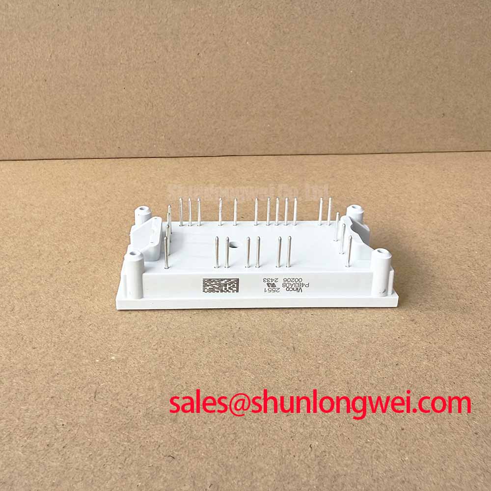
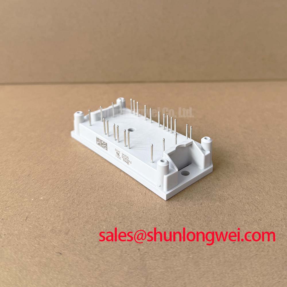
When a robotic-axis drive trips during acceleration or regenerative braking, I first isolate the DC link, record the fault timing, and compare the gate-drive and collector-emitter waveforms with a known-good channel. The P843A08 is a Vincotech PIM configuration combining rectifier, braking, and inverter functions. Its official collector-emitter voltage rating is 600 V, while the listed collector current is 30 A at Tc = 80°C. These values identify the device class; they do not replace switching-test verification inside the complete drive.
Desaturation protection is a control-system function that detects an abnormal rise in the IGBT collector-emitter voltage while the gate command is active. For a short-circuit event, the protection circuit should distinguish a genuine overcurrent condition from a switching transient, then remove the gate command without creating a second damaging voltage excursion. A two-stage soft turn-off sequence is a useful Design Consideration: the driver can first reduce gate drive in a controlled manner and then complete turn-off while monitoring the resulting collector-emitter overshoot. Any response target, including a sub-10 microsecond protection objective, must be established by the gate-driver design and verified under the applicable short-circuit operating area conditions rather than treated as a factory rating of this module.
Keep the high-current commutation loop compact and physically separated from the gate-drive return. The auxiliary emitter or gate-return path should not share a long power-current trace, because common impedance can shift the driver reference during rapid current change. Where the module provides a separate auxiliary emitter terminal, route that return directly to the driver reference according to the module and driver pin definitions. The P843A08 listing confirms the module topology, but it does not define a universal gate-driver pinout for every system implementation.
During commissioning, use a differential voltage probe across the relevant power terminals and a current probe on the switching path. Check whether the fault appears at turn-on, during steady conduction, or at turn-off. A fault that occurs only after thermal rise can point toward cooling, gate-drive supply stability, or timing interaction rather than a single component failure. Compare the desaturation blanking interval, soft turn-off behavior, and gate voltage at the module terminals. The test setup should also reproduce the actual DC-link capacitance, busbar arrangement, motor cable, and braking path, since each changes the transient seen by the protection circuit.
Common-mode transient immunity is another practical concern for industrial inverter control boards. Optical isolators and digital isolators respond differently to fast common-mode movement, so the control designer should evaluate the chosen isolator, gate driver, shielding, and return-current path as one system. Keep control wiring away from the rectifier and inverter power loops, and validate the driver supply during the same switching event used to check desaturation behavior.
For maintenance teams comparing alternative devices, MG30G6EL2 can be reviewed separately, without assuming compatibility. Electrical ratings, topology, terminal geometry, gate-drive requirements, and thermal behavior still require a documented engineering comparison before substitution.
Preventing Spurious Faults: Thermal Cycling Margins of Internal Braking Guidelines for P843A08
The braking circuit and external braking resistor must dissipate the kinetic energy returned by a decelerating motor without allowing the DC link to rise beyond the system’s permitted operating boundary. The P843A08 uses a PIM topology with an integrated braking function, but the module rating alone does not determine the required ballast resistor, braking duty, or allowable regenerative profile. Those values depend on motor inertia, commanded deceleration, DC-link capacitance, duty cycle, ambient temperature, and the cooling assembly.
For a multi-joint robotic articulator, examine each axis separately before combining the worst-case energy at the shared DC link. A high-inertia joint may create a short, intense braking pulse, while several axes can produce overlapping regeneration. The braking resistor and its switching device should therefore be assessed using the actual energy waveform rather than only its average power. This is an Engineering Recommendation: calculate the resistor’s pulse energy and thermal recovery behavior from the motion profile, then verify the DC-link rise during representative emergency stops and repeated production cycles.
The integrated NTC thermistor provides a practical temperature-monitoring point for the module assembly. Connect it to the drive controller or monitoring circuit according to the control architecture, and trend the measured temperature against load, switching frequency, cabinet temperature, and airflow condition. An NTC reading is valuable for detecting thermal drift, but it should not be used as a substitute for checking semiconductor junction-temperature limits or the thermal impedance of the complete mounting stack.
Switching frequency changes the balance between conduction loss and switching loss. At operating points from approximately 2 kHz to 16 kHz, the correct evaluation method is to record module temperature, case temperature, braking activity, and fault history under the actual motor profile. Do not apply one derating curve to every axis or assume that a lower motor current automatically produces a lower module temperature. Short braking pulses can create a different transient thermal response from steady inverter operation, particularly when the heatsink and thermal interface have not reached equilibrium.
Inspect the heatsink fins, fan path, and interface material during scheduled service. Uneven mounting pressure, aged thermal compound, contamination, or condensation can raise the thermal resistance between the module case and heatsink. ⚠️ Maintenance Note: Monitor contact temperature during representative motion cycles and verify the cooling airflow after cleaning or fan replacement.
When a braking fault appears only after repeated stops, review the energy sequence and thermal recovery time before changing protection thresholds. The fault may involve resistor heating, DC-link measurement drift, brake command timing, or insufficient airflow. Measure the DC-link waveform at the power terminals with suitable isolation and bandwidth, and compare the captured energy profile with the resistor and braking-device design records. The P843A08’s official current specification is 30 A at Tc = 80°C; the permissible braking duty in a finished drive remains system-dependent.
For broader context on switching technologies and their layout implications, the engineering team may consult Wide Bandgap Revolution. The article is a technology reference, not a statement that this silicon IGBT module contains wide-bandgap semiconductor technology.
Preventing Spurious Faults: Output Sinusoidal Filter vs dv/dt Reactor Guidelines for P843A08
Long motor leads can create a transmission-line interaction between the inverter output and the motor terminals. If the cable impedance, motor impedance, and switching edge are poorly matched, the motor-end voltage can rise substantially and may approach twice the local step voltage in an unfavorable reflection condition. This is a system-level Design Consideration, not a guaranteed behavior or a specified terminal voltage for the P843A08.
Choose between a dv/dt reactor and a sinusoidal filter according to the motor insulation requirement, cable arrangement, switching pattern, and control bandwidth. A reactor reduces the steepness of the voltage transition and can limit cable-reflection stress while retaining a PWM waveform at the motor. A sinusoidal filter reshapes the waveform more extensively and may reduce motor insulation stress and acoustic effects, but it introduces additional impedance, loss, heat, and control-response considerations. The filter manufacturer’s voltage, current, frequency, and installation requirements must be checked alongside the inverter module ratings.
Place the selected output network with enough physical separation from sensitive feedback and gate-drive wiring to limit capacitive coupling. Keep the three motor conductors grouped consistently, maintain the intended protective-earth path, and avoid routing encoder or resolver cables in parallel with high dv/dt conductors for long distances. The final clearance and creepage arrangement should follow the applicable equipment insulation design and enclosure conditions; they are not fixed by the P843A08 part number.
During troubleshooting, capture the inverter-side and motor-side phase-to-phase waveforms under the cable length and load condition that produces the fault. A high reading at the motor but not at the inverter can indicate cable reflection or filter interaction. A high reading at both locations requires examination of the DC link, commutation loop, gate resistance, probe connection, and switching timing. Use the same probe method at both measurement points, because an unsuitable ground lead can create a measurement artifact that resembles a real overshoot.
Thermal checks must include the reactor or filter, not only the IGBT module and heatsink. Added output impedance can alter motor current ripple or the current-controller response, while a sinusoidal filter can draw reactive current depending on its topology. Confirm that the drive remains stable through acceleration, constant-speed operation, deceleration, and rapid direction changes. If a filter is installed after commissioning, repeat the desaturation and braking tests because the modified output network changes the switching environment.
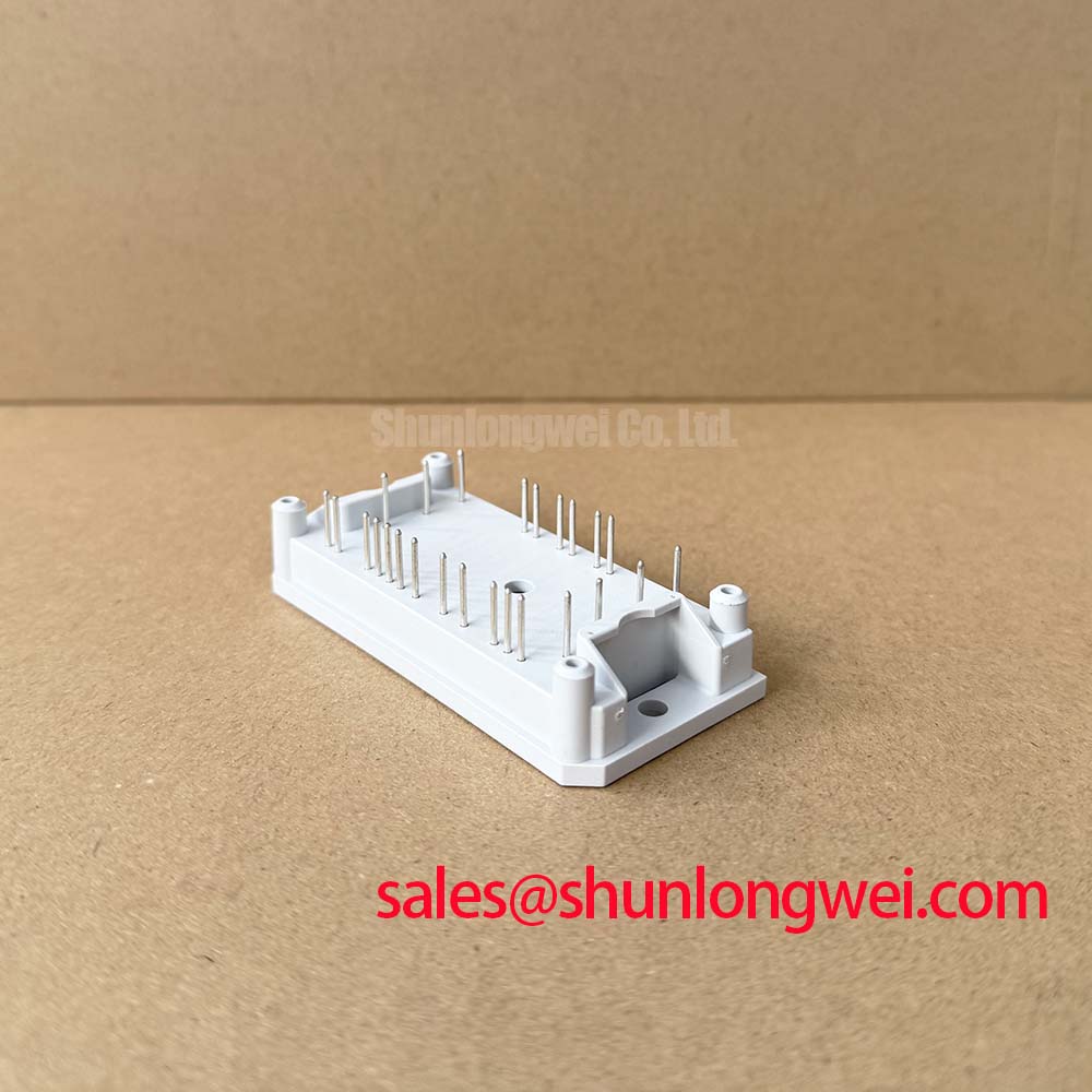
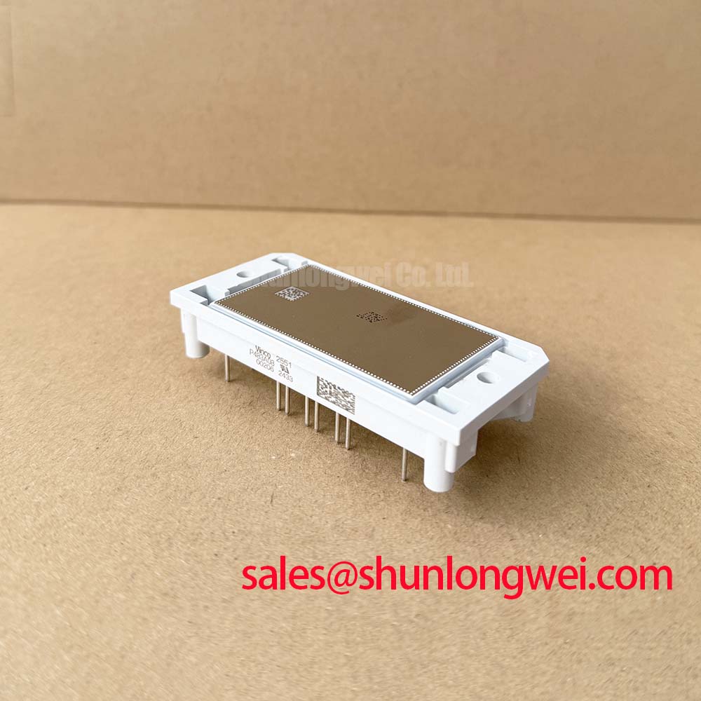
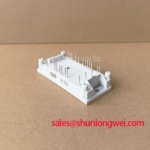
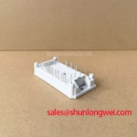
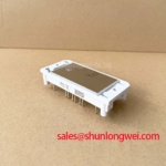
The flow 1 flowPIM housing, integrated NTC, low-loss IGBT technology designation, and rectifier, brake, and inverter arrangement make the P843A08 suitable for evaluation in compact industrial drive assemblies, including light automation equipment and multi-joint robotic actuator drives. Final acceptance should be based on measured voltage stress, thermal behavior, protection response, and mechanical compatibility within the target cabinet.