Content last revised on September 18, 2026
PE55F80 Identification and Cold Testing
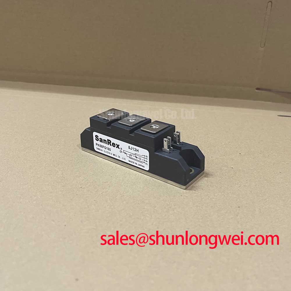
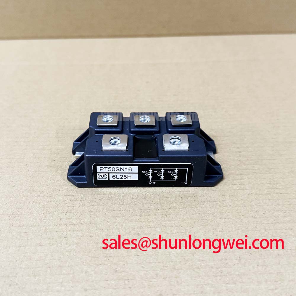
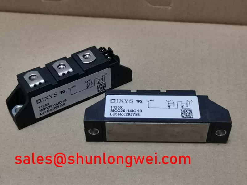
With the equipment isolated and discharged, first verify the nameplate boundary of PE55F80 against the failed assembly, then inspect the isolated base, power terminals, hardware contact faces, and surrounding busbar clearance before any electrical test. The available official factory data identifies this Nihon Inter device as an Isolated Power Module rated at 2500V and 55A. These are Official Datasheet Specifications and should be treated as the primary identity checks during replacement assessment.
For cold testing, disconnect external gate, control, snubber, and load wiring where the equipment procedure permits. Measure terminal relationships with a meter using the original circuit diagram as the reference. A reading affected by parallel suppression parts, fuses, transformers, or other semiconductor paths cannot by itself establish the condition of the module. Compare the disconnected result with the known circuit topology and, when available, a verified working phase or channel.
| Parameter | Declared Value | Status |
|---|---|---|
| Model | PE55F80 | Official product identification |
| Manufacturer | Nihon Inter, NIEC | Official manufacturer identification |
| Rated voltage | 2500V | Official Datasheet Specification |
| Rated current | 55A | Official Datasheet Specification |
| Package | Isolated Power Module | Official Datasheet Specification |
| Product classification | Thyristor / Diode Module | Category reference, confirm internal circuit arrangement from original documentation |
Transient Dynamics & Electrical Design: Commutation and Voltage Overshoot on PE55F80
The first repair question is whether the removed module was operating in a line commutated rectifier position, a controlled rectifier bridge, or another power conversion leg. The 2500V and 55A ratings define the official device boundary, but they do not disclose the internal circuit configuration, reverse recovery current, reverse recovery time, switching waveform, or allowable gate drive conditions. The system integrator should verify these details from the original PE55F80 documentation and the equipment schematic before copying a firing board or snubber arrangement from another module family.
In a high current green hydrogen electrolyzer DC power rectifier, current commutation through diodes and controlled semiconductor paths can create voltage excursions at the busbar and terminal level. Design Consideration: keep the intended commutation path physically compact and maintain clean, broad electrical contact surfaces to reduce parasitic inductance that can add overshoot during current transfer. The actual peak voltage must be verified under switching or commutation test conditions against the DC link, AC supply, snubber network, and the official 2500V module rating.
Reverse recovery behavior is particularly relevant when a rectifier section includes a diode path that must recover before reverse voltage is reapplied. Parameters such as peak reverse recovery current and recovery softness cannot be inferred from the PE55F80 current rating. A sharp transient at the module terminals may indicate interaction among the commutating device, transformer leakage inductance, busbar geometry, snubber condition, and measurement probe arrangement. Capture terminal voltage and current with an appropriately rated differential measurement method, then compare timing with a known healthy section where practical.
A failed RC snubber, open capacitor, damaged resistor, loose terminal connection, or altered wiring path can change the observed transient without proving that the module is the initiating cause. Engineering Recommendation: inspect each associated suppression component for value drift, physical damage, heat discoloration, and secure connection before returning a replacement module to service. The system engineer should validate dissipation and peak voltage during the relevant load transition rather than relying on no load checks alone.
The PE55F80 official data supplied here does not provide fuse I²t coordination values. Fuse selection must therefore remain a system level decision based on the equipment fault study, prospective current, semiconductor protection requirement, and verified protective coordination documentation. Do not assign a fuse from the module’s 55A rating alone. A fuse that remains intact during one event may still provide inadequate semiconductor protection in a different commutation or overload condition.
Power module topology varies significantly across industrial rectifier products. For neutral background on how power modules consolidate semiconductor functions and interconnections, see Power Module Architecture & Topologies. This reference is useful for terminology, while the PE55F80 terminal arrangement and ratings must be confirmed only from the original equipment documentation and applicable manufacturer data.
PE55F80 Circuit Protection & Reliability: Preventing Localized Gate Hotspot Burnout
Before reconnecting any control plug, establish whether the PE55F80 installation actually uses gate fired semiconductor paths. The supplied official parameter set confirms an isolated power module but does not provide gate terminal identification, trigger current, trigger voltage, holding current, latching current, gate pulse rise time, repetitive pulse capability, or a multi pulse firing specification. These values must not be guessed from the part number or transferred from a visually similar module.
Where the original circuit documentation confirms a thyristor controlled path, the firing board must deliver the intended pulse at the module terminals rather than only at the controller output connector. Cable resistance, corroded contacts, shared return routing, loose terminal hardware, and a degraded pulse transformer can alter the actual gate waveform. A scope comparison between a known healthy channel and the suspect channel is more useful than treating a single static resistance measurement as final proof of gate circuit condition.
Design Consideration: separate high current commutation paths from low energy firing and sensing paths where the original design provides separate routing. This reduces the risk that fast current changes and common mode voltage movement disturb the trigger reference. The required separation, conductor route, pulse width, trigger level, and firing sequence are determined by the original control topology and must be validated by the responsible system engineer.
In phase controlled rectification, uneven firing among parallel or bridge positions can contribute to unequal electrical stress. The underlying cause can reside in control synchronization, isolation circuitry, gate distribution, supply ripple, a damaged snubber, or the module itself. Check the timing reference, channel to channel pulse consistency, terminal tightness, and measured current sharing before deciding that a replacement power module alone resolves the fault.
Holding current and back porch behavior are often discussed during controlled rectifier troubleshooting, yet no PE55F80 factory value for either parameter is available in the supplied data. Treat any assumed threshold as unsuitable for this model. Observe the current waveform and conduction continuity under the equipment’s approved test conditions, and use the original rectifier control documentation to determine whether a delayed or repeated firing pulse scheme is required.
⚡ Field Alert: Isolate all stored energy and follow the equipment’s lockout procedure before removing gate or power connections, because an apparently inactive rectifier assembly can retain hazardous charge through connected capacitors and external circuits.
When comparing package candidates, the current and voltage figures are only part of the decision. The replacement must also match circuit function, terminal map, isolation arrangement, mechanical footprint, thermal interface, and control connections. The PGH50N16 is a separately listed product that can be reviewed as a neutral comparison reference, but it should not be treated as an automatic substitute for PE55F80. The original circuit documentation and measured operating conditions determine whether any alternative is electrically and mechanically compatible.
Assembly Integrity & Layout Architecture: Surge and Thermal Considerations for PE55F80
Inspect the PE55F80 mounting plane before installation. Remove old residue without damaging the isolated base or heatsink surface, confirm that the heatsink is flat and free of raised burrs, and check that the module sits without rocking before final tightening. An uneven interface can raise thermal resistance locally, while a loose power connection can create heat at the terminal rather than within the semiconductor junction.
The supplied official data does not state an ITSM surge current rating, an I²t value, a junction temperature limit, a thermal resistance value, or a manufacturer mounting torque. Do not assign these values from general module dimensions or from another Nihon Inter part. The correct mounting hardware, tightening sequence, torque, thermal compound method, and heatsink requirement must be taken from the original PE55F80 documentation or the equipment manufacturer’s service specification.
Engineering Recommendation: apply thermal interface material as a controlled, uniform thin layer where the system procedure calls for it, then tighten fasteners in a balanced sequence. This is a general assembly practice, not an official PE55F80 torque specification. After the first controlled thermal cycle, inspect for terminal settlement, hardware loosening, compound displacement, and abnormal heating at the busbar joint.
For systems exposed to repetitive current peaks, do not interpret the nominal 55A rating as permission for uncontrolled surge operation. A sinusoidal half cycle surge event, a transformer energization event, a downstream DC fault, and a commutation fault impose different electrical and thermal conditions. The system protection design should be verified using the applicable fuse coordination data, transformer characteristics, conductor impedance, and confirmed module surge capability.
Before reverse voltage is reapplied after a surge or fault event, examine whether the fault was cleared throughout the full current path. A module that appears acceptable at room temperature can still be associated with damaged suppression parts, overheated joints, or an upstream control sequence issue. Inspect the heatsink, terminal hardware, fuse assembly, snubber network, and adjacent modules as a connected system.
Creepage and clearance around a 2500V rated module require particular care. Design Consideration: preserve the equipment’s original physical spacing, insulating barriers, covers, and cable support arrangement. Dust, moisture, conductive debris, unsupported busbars, and altered terminal orientations can reduce the practical insulation margin. The final clearance assessment depends on the enclosure environment, pollution conditions, system voltage waveform, and applicable equipment standards.
PE55F80 Operational Boundaries: Evaluating AC Line Surge Immunity and Lightning Transient Limits
Start surge diagnosis at the AC input and work toward the PE55F80 position. Record the condition of upstream fuses, contactors, line reactors, transformer connections, MOV assemblies, RC suppression circuits, grounding conductors, and DC bus components. A damaged MOV or snubber can be evidence of a surge event, but it does not by itself establish the amplitude, origin, or energy of that event.
The PE55F80 is officially rated at 2500V, yet that value must not be presented as a complete statement of AC line surge immunity. The supplied information does not provide an impulse withstand value, lightning surge classification, EMC certification, isolation test specification, or protection coordination requirement. Surge performance belongs to the complete rectifier assembly, including the AC source impedance, transformer, protective devices, wiring layout, enclosure bonding, and load response.
Where the equipment protection design uses MOVs, their selection must consider the normal line condition, expected temporary overvoltage behavior, energy exposure, coordination with upstream protection, and the clamping requirement of the complete circuit. Where it uses RC snubbers, the required capacitance, resistance, voltage capability, and placement must be derived from measured commutation behavior and original equipment documentation. These are Design Considerations, not PE55F80 factory settings.
In electrolyzer rectifier service, supply disturbances can also affect firing synchronization and conduction angle. Inspect voltage sensing references, synchronization wiring, controller supply stability, and phase current waveforms after a surge related trip. Distorted input current can arise from several interacting causes, including control timing error, transformer saturation, unequal bridge conduction, or changed load conditions. Test results should be evaluated against the equipment’s approved operating waveform and protection logic.
For broader power semiconductor context, SanRex Sansha Electric Power Semiconductor Modules provides industry reference material on power semiconductor product categories. For technicians who also maintain industrial monitoring systems around high power rectifier cabinets, The Ultimate Guide to Industrial TFT LCD Technology can support display interface and panel selection checks. Neither reference replaces PE55F80 specific documentation when setting protection limits or approving a module replacement.