

Content last revised on September 28, 2026
Benchtop Waveform Tuning and Short Circuit Coordination for PGH10016AM
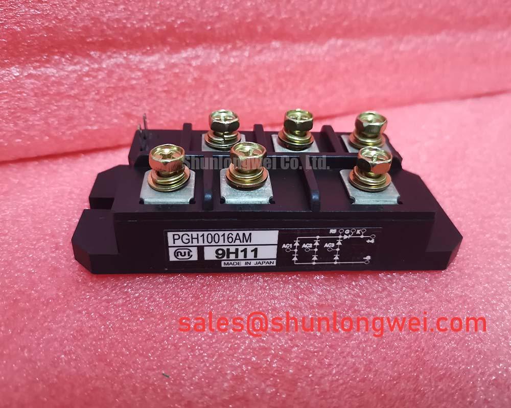
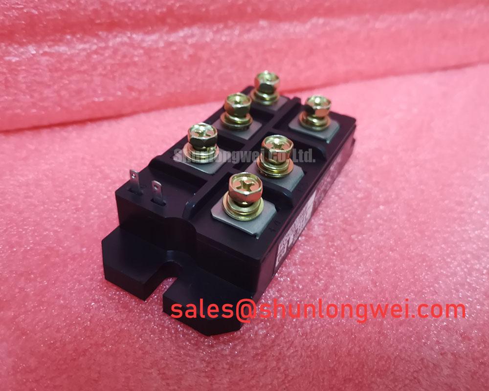
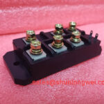
With the equipment isolated and the DC link discharged, compare the installed module’s terminal markings and mounting footprint with the replacement documentation before removing a power lead. PGH10016AM from Nihon Inter (NIEC) is an isolated power module in the thyristor and diode category. Its supplied official specifications are 1600 V rated voltage and 100 A rated current. Those ratings establish a starting boundary for evaluation; they do not establish terminal interchangeability, fault withstand, or suitability for a particular switching circuit.
Begin with the equipment schematic and the module terminal diagram. Identify the power terminals, any control terminals, the fuse position, and the return path used by the measurement instrument. Record the installed connections before disturbing them. A cold continuity check can expose an unexpected low impedance path, but it cannot establish a thyristor’s dynamic behavior or confirm that a diode will withstand service conditions.
For a medium frequency induction melting or hardening furnace under compatibility review, the 1600 V and 100 A ratings are official specifications of PGH10016AM, not permission to reuse the existing fuse. A short circuit coordination assessment needs the candidate fuse’s published clearing I²t at the relevant circuit conditions and the module’s documented surge or nonrepetitive fault limit. No such module limit or fuse coordination table is supplied here. Consequently, Type 2 coordination and damage free clearing cannot be claimed for a dead short. The maintenance team should obtain both manufacturers’ curves, check the available fault current, and have the system protection engineer assess the result before energization.
When comparing parts, PGH50N16 provides a related model for a specification review, not an established drop in replacement. Compare its manufacturer terminal drawing, mechanical footprint, voltage and current definitions, and protection limits against those of PGH10016AM and the installed assembly. Do not infer equivalent fuse coordination from a similar model name.
PGH10016AM Circuit Protection: Snubbers, Reactors and Terminal Checks
Inspect the existing snubber and any series reactor as parts of the equipment circuit, rather than as features guaranteed inside PGH10016AM. Check the snubber resistor and capacitor for the values shown on the equipment drawing, then inspect their connections for looseness or heat discoloration. Compare captured voltage and current waveforms with a known good operating record, using measurement practices appropriate to the circuit voltage. A changed waveform can have several causes, including a degraded snubber connection, altered load conditions, or a control timing fault; the trace alone does not identify the failed part.
Design Consideration: Snubber resistance and capacitance should be selected against measured transient voltage and the device limits documented for the actual circuit. A series saturable reactor, where the equipment design includes one, should be assessed against measured current rise and its own manufacturer data. Neither component can be sized from the 1600 V and 100 A nameplate ratings alone. The system designer must validate the resulting margins under representative switching and fault conditions.
If the surrounding converter includes a driven switching stage, inspect its control supply and return routing separately from this module’s confirmed specifications. Gate bias, common mode ground noise, bootstrap capacitor recharge, and diode recovery belong to the particular driver and topology; they are not established PGH10016AM parameters. The Miller effect is relevant when evaluating unintended switching in voltage driven transistor stages, but should not be treated as proof of a PGH10016AM failure mechanism. For a system drawing that includes a separate rectification stage, DDB6U180N16RRP_B37 is another device whose documented role and ratings can be reviewed independently.
Baseplate Contact and Thermal Inspection for PGH10016AM
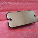
Before mounting, clean the mating surfaces and inspect the heatsink for contamination, raised burrs, or damage that could prevent even contact. Check how the existing thermal interface material has spread, then apply the replacement material according to the equipment and material instructions. Tighten the mounting hardware in the sequence and to the torque stated in the applicable mechanical documentation. A mounting torque and junction to case thermal resistance for PGH10016AM have not been supplied here, so neither should be represented as an official specification.
Maintenance Note: With power isolated, inspect the heatsink air path and terminal tightness during scheduled maintenance, and investigate a rising contact temperature rather than compensating for it by overtightening the module.
Design Consideration: Stable thermal contact depends on surface condition, interface material, and mounting pressure across the module footprint. To assess thermal performance, log operating current, accessible case or heatsink temperature, cooling conditions, and the location of each measurement. Compare the results with the equipment baseline and the manufacturer’s thermal limits once the relevant PGH10016AM documentation is available. A warm terminal can warrant a separate connection inspection; it does not, by itself, establish a junction temperature or identify an internal defect.
Where service history prompts a reliability review, distinguish observed external symptoms from unverified internal construction. Wire bonding explains a packaging method used across semiconductor products, but the supplied PGH10016AM information does not identify its internal interconnect method. Record temperatures, load changes, cooling maintenance, and connection work instead of attributing a symptom to an unseen structure.
Field Diagnostics and Surge Rating Verification for PGH10016AM
For a unit removed after a trip, document the protection indication and circuit conditions before resetting the equipment. After isolation and discharge, compare terminal to terminal cold measurements with the equipment procedure or a documented known good assembly. Inspect external terminals, the mounting surface, fuse, snubber connections, and cooling path. During controlled recommissioning, capture current and voltage at points defined by the equipment test plan; investigate differences without assuming that a single symptom has a single cause.
The 100 A rated current is an official PGH10016AM specification, but it is not an ITSM surge rating. No PGH10016AM surge current value, test pulse condition, initial junction temperature, or reverse voltage reapplication condition has been supplied. A sinusoidal half cycle surge assessment therefore requires the original manufacturer’s stated ITSM conditions and the equipment’s measured fault waveform. Repetitive events must be evaluated against the relevant documented limits, not treated as repeated permission to use a nonrepetitive rating.
For induction heating equipment, the distinction between circuit topologies also matters when interpreting a trip trace. Resonant Topologies in Home Appliances offers background on quasi resonant and half bridge behavior; the installed furnace schematic remains the authority for identifying its actual topology. Before returning the equipment to service, have the responsible engineer compare the recorded transient, cooling condition, protection settings, and PGH10016AM manufacturer limits, including any specified junction temperature requirements before reverse voltage is reapplied.