Content last revised on October 2, 2026
Field Diagnostics & Commissioning: Off-State Voltage Rise in PK55F160 Topologies
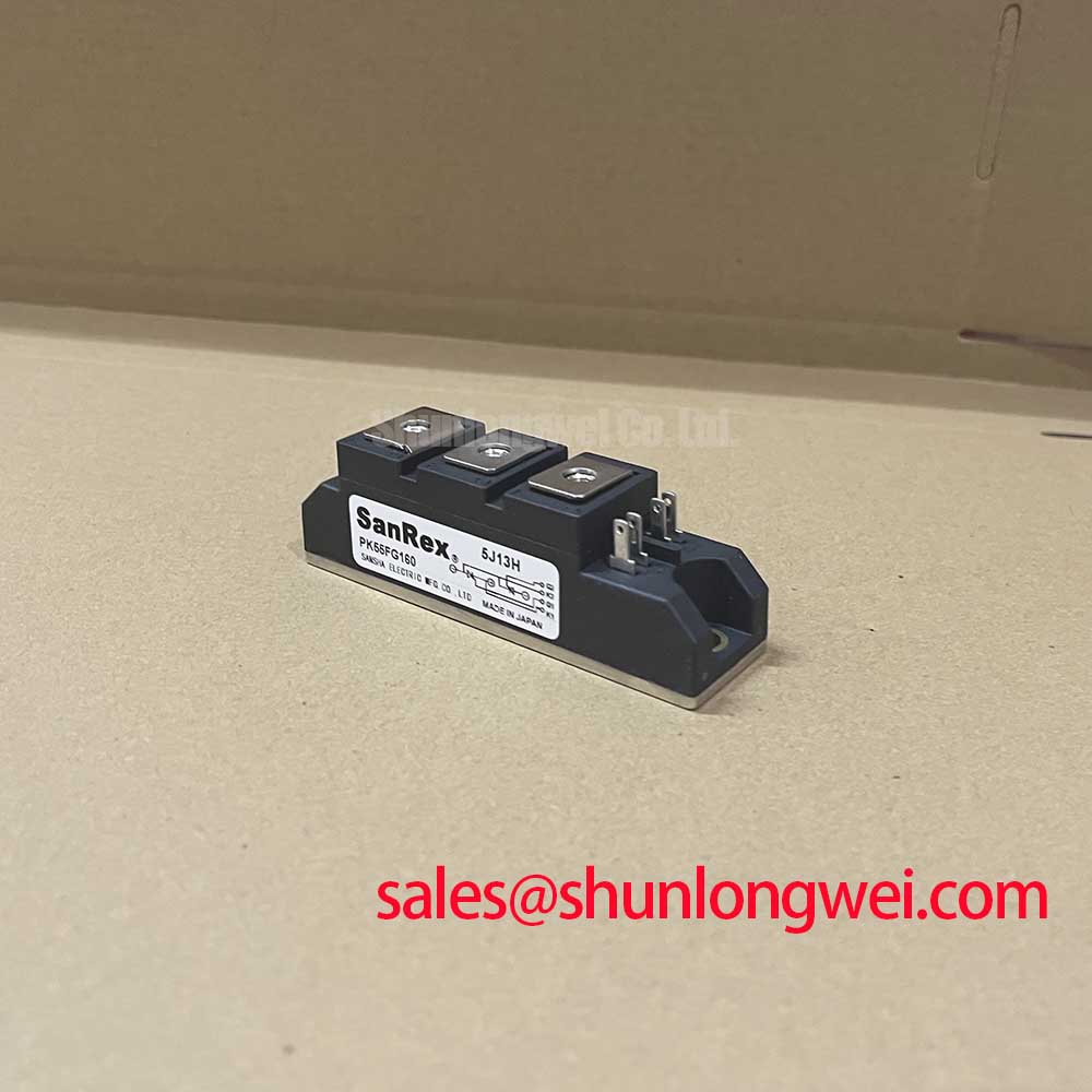
The SanRex (Sansha Electric) PK55F160 is specified at 1600 V rated voltage and 55 A rated current, in an Isolated Power Module package (Official Specification). Those figures establish an initial identification check, not a complete replacement decision. Confirm the original circuit drawing, terminal arrangement, mounting pattern and required operating conditions before transferring connections. The stated package description does not establish an insulation test voltage, so enclosure and heatsink requirements still need verification against the equipment documentation.
Start the cold inspection at the connections. Look for loosened lugs, discolored contact faces, damaged terminal threads and uneven seating against the heatsink. Measure comparable terminal pairs with the same meter range and lead orientation, keeping the gate circuit disconnected only where the equipment procedure permits it. Readings that differ from a documented baseline warrant investigation of both the module and the surrounding circuit; parallel snubbers and transformer windings can otherwise make an in-circuit reading misleading.
During commissioning, an unexpectedly rapid rise in off-state voltage can contribute to unintended thyristor triggering. That is a Design Consideration, not a stated PK55F160 dv/dt limit: no model-specific critical rate of rise is supplied here. If the equipment uses an RC snubber, inspect its resistor, capacitor and connections against the original schematic before attributing a firing fault to the module. Size or revise that network only from measured waveforms, the applicable device documentation and the rectifier’s voltage and thermal limits. Where a series saturable reactor is part of the existing design, check its connections and condition as well; do not add one on the strength of a cold meter test.
Field Alert: Keep the DC link discharged during terminal work, and use the equipment-approved fastener torque rather than an assumed torque for this package.
Transient Dynamics & Electrical Design: Gate Triggering Across Temperature
Trace the firing path from the controller through its isolation stage to the PK55F160 gate terminals shown on the original wiring diagram. An intact power path does not prove that a gate pulse arrives with the required polarity, amplitude or timing. For an intermittent firing complaint, capture the command and gate waveforms under an approved test procedure, then compare them with a documented working channel at similar operating conditions. Check connector seating and gate-return continuity before changing the firing circuit.
Gate trigger current can depend on junction temperature, and a weak or poorly timed pulse may fail to establish conduction consistently. The thyristor operating principle explains why triggering, latching and subsequent current flow must be considered together. That principle does not supply a PK55F160 gate-current rating. No factory gate-pulse rise rate, back-porch current or multi-pulse firing requirement is established by the supplied specifications, so treating any of them as a mandatory setting for this module would be unjustified.
As a Design Consideration, examine the gate waveform alongside the associated power-terminal current when diagnosing uneven firing. The system designer determines whether a sustained portion of the pulse or repeated pulses are appropriate, using the original gate-drive specifications and tests across the intended temperature range. This matters particularly when the equipment has been idle in a cold plant room: a successful warm restart does not, by itself, clear a cold-start firing complaint.
Replacement evaluation also needs more than matching the printed current rating. PK55FG120 is a related model to examine in a cross-model comparison, not an established drop-in substitute. Compare its documented circuit arrangement, terminal locations, gate requirements, voltage and current conditions, thermal interface and mechanical fit with those of the installed PK55F160 before considering a change.
PK55F160 Operational Boundaries: Assessing Surge Exposure
At an AC-fed rectifier, separate an input surge event from a gate-control fault before replacing the power module. Review protection-device condition, controller fault records and captured line or DC-link waveforms where available. A damaged surge protector or snubber may coexist with a damaged module; replacing only the module would leave the source of stress unresolved. The 1600 V PK55F160 rating (Official Specification) must be checked against the relevant voltage across the device under the equipment’s actual switching and fault conditions, rather than against nominal input voltage alone.
IEC 61000-4-5 concerns surge-immunity testing of equipment; it is not an independent immunity certification for this module. As a Design Consideration, evaluate metal oxide varistors and existing RC stages as parts of the complete AC-input protection scheme. Their placement and ratings depend on the rectifier topology, prospective surge conditions and coordination with upstream protection. A commissioning test should verify that measured transients remain within the applicable device and system limits. The supplied PK55F160 specifications do not state a surge-immunity level or a prescribed varistor size.
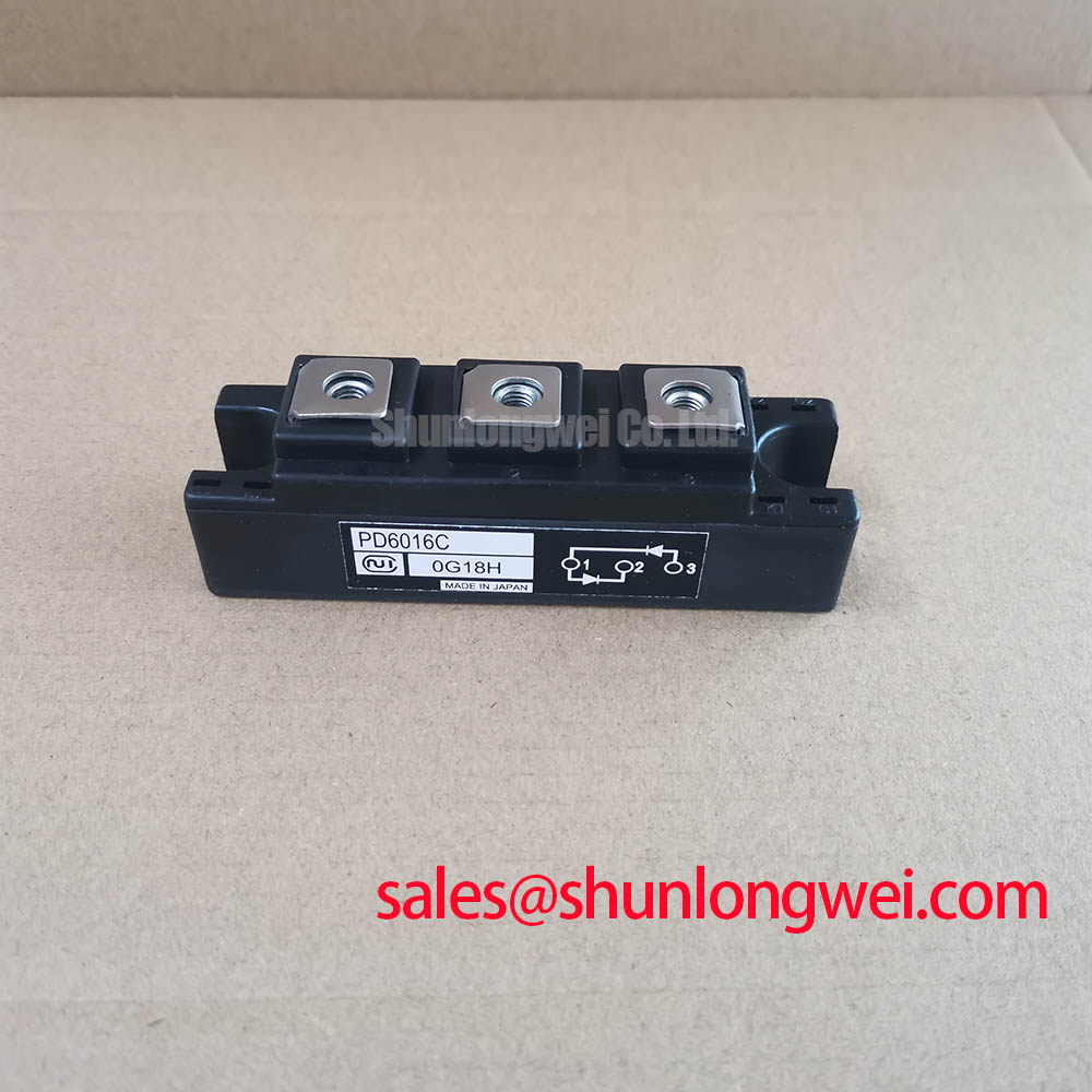
Follow the power path on the drawing rather than assuming every module occupies the same rectifier position. A related module such as PD25016A can be reviewed when identifying an adjoining rectification stage, but its role and compatibility must be established from the particular circuit. Engineers evaluating a high-current green hydrogen electrolyzer DC rectifier, for example, should map the installed module’s terminals and protective components to that equipment’s drawings before assessing PK55F160 fit.
PK55F160 Circuit Protection & Reliability: Checking Peak-Current and Thermal Margins
After a suspected overcurrent, inspect the semiconductor fuse and its connections before drawing conclusions from the module’s cold resistance. Compare the fuse’s documented let-through behavior with the PK55F160 surge-current and I²t data in the applicable manufacturer documentation. A 55 A rated current (Official Specification) cannot stand in for a nonrepetitive surge rating, and no PK55F160 ITSM, I²t value or fuse-coordination table is established by the supplied specifications. Do not assign a protective fuse solely from the steady-current figure.
If the rectifier assessment calls for a sinusoidal half-cycle surge check, obtain the device’s stated test conditions before comparing that event with a captured fault. Initial junction temperature, waveform, pulse duration and subsequent reverse-voltage application all affect whether the comparison is valid. The practical check is to align the equipment’s recorded event with the manufacturer’s specified conditions and the fuse data, then have the system engineer verify thermal and voltage margins. Describing this as a guaranteed “thermal avalanche margin” would imply a PK55F160 limit that has not been supplied.
For a return-to-service decision, examine the heatsink contact, mounting hardware, airflow path and temperature records alongside the electrical fault evidence. Reapply the equipment-approved mounting procedure if the module has been disturbed; the package label alone supplies neither a torque value nor an allowable case temperature. Reliability or service-life claims require separate evidence. The Wide Bandgap Revolution article provides background for technology comparisons, but it does not establish a lifetime or qualification result for PK55F160.