Content last revised on February 25, 2026
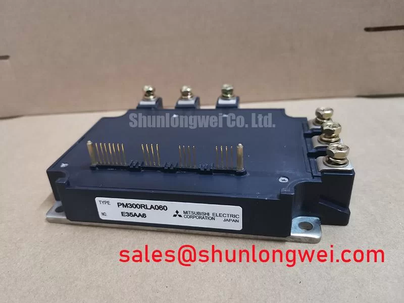
PM75RHA060 Mitsubishi 600V 75A Intelligent Power Module (IPM)
The PM75RHA060 is a high-performance Intelligent Power Module (IPM) designed by Mitsubishi Electric, specifically engineered to simplify complex power stage designs while ensuring maximum operational uptime. By integrating high-speed, low-loss IGBT chips with sophisticated on-chip control logic and protection circuits, this module eliminates the design overhead of discrete gate drive stages. Featuring a 600V collector-emitter voltage and a 75A collector current rating, it serves as the reliable backbone for mid-power industrial motor control and inverter systems.
Top Specs: 600V | 75A | Vce(sat) 2.1V (Typ.) | Rth(j-c) 0.52°C/W (IGBT)
Key Benefits: Integrated protection against short circuits and over-temperature; significant PCB space reduction via integrated gate drive.
What is the primary benefit of its integrated drive logic? It minimizes parasitic inductance and electromagnetic interference (EMI) by locating the gate driver in immediate proximity to the power chips. For industrial drives prioritizing thermal margin and fault resilience, this 75A module is the optimal choice.
Key Parameter Overview
Decoding the Specs for Enhanced Thermal Reliability
The technical excellence of the PM75RHA060 is best understood through its balanced electrical and thermal characteristics. The following data is derived from official engineering documentation to assist in precision system sizing.
| Functional Category | Parameter Symbol | Typical / Max Value | Engineering Significance |
|---|---|---|---|
| Power Stage | Vces (Collector-Emitter Voltage) | 600V | Ensures robust headroom for 240V/380V AC line rectification. |
| Power Stage | Ic (Continuous Collector Current) | 75A (at Tc=25°C) | Supports 5.5kW to 7.5kW motor drive applications. |
| Efficiency | Vce(sat) (Saturation Voltage) | 2.1V (Typ.) | Directly influences conduction losses in high-duty cycle operations. |
| Protection Logic | Vot (Over-Temperature Trip) | 111°C - 125°C | Automatic shutdown threshold to prevent catastrophic silicon failure. |
| Isolation | Viso (Isolation Voltage) | 2500V AC (60Hz, 1 min) | Meets rigorous safety standards for operator and control logic protection. |
Application Scenarios & Value
Achieving System-Level Benefits in High-Frequency Power Conversion
In modern industrial environments, the PM75RHA060 is frequently deployed in Variable Frequency Drives (VFD) and Servo Drive systems. Consider the engineering challenge of an automated packaging line where a conveyor motor must handle sudden mechanical load spikes. A standard discrete IGBT might succumb to thermal runaway if the cooling system lags. However, the PM75RHA060 utilizes its internal Short-Circuit Safe Operating Area (SCSOA) logic to detect over-current conditions within microseconds, pulling the Fault Output (FO) pin low to alert the system controller before hardware damage occurs.
Beyond standard motor control, this module is a staple in Uninterruptible Power Supplies (UPS) and Solar Inverters. For designs requiring even higher power density or current handling, the PM150CVA120 offers a 1200V alternative for 480V systems. Integrating this IPM simplifies the Gate Drive layout, reducing the total bill of materials (BOM) and improving the Power Cycling Capability of the final assembly.
By leveraging Mitsubishi CSTBT™ technology, engineers can achieve a tighter control loop and better energy efficiency, aligning with IEC 61800-3 EMC standards and carbon-neutral manufacturing goals. This module is more than a switch; it is a self-protecting power stage that ensures long-term industrial reliability.
Technical & Design Deep Dive
Intelligent Protection Logic: The Module's Internal Safeguard
What truly distinguishes the PM75RHA060 from a traditional IGBT Module is its "Intelligent" layer. While a standard module acts like a high-power muscle, the IPM includes the "brain" and "nervous system" directly on the substrate. To visualize this, imagine a high-performance engine that not only provides torque but also has a built-in sensor that instantly cuts fuel if it detects an oil pressure drop—without waiting for an external dashboard signal.
Technically, this is achieved through a Low-side Control Supply Under-Voltage (UV) protection and Over-Temperature (OT) sensing located directly on the IGBT chip. The OT protection monitors the baseplate temperature, ensuring the module stays within its Safe Operating Area. Furthermore, the Current Sense IGBT architecture allows for real-time monitoring of the collector current with negligible loss compared to external shunt resistors. This integration significantly reduces parasitic inductance, which is a major driver of voltage overshoots during high-speed switching transitions.
For a detailed breakdown of how these components interact at a system level, engineers may reference our guide on IPM vs. Discrete IGBT design strategies. Understanding the Thermal Resistance (Rth(j-c)) is also critical; at 0.52°C/W, the PM75RHA060 requires careful Thermal Management and heatsink selection to maintain peak 75A performance under continuous load.
FAQ
How does the Rth(j-c) of 0.52°C/W directly impact heatsink selection and overall system power density?
The Rth(j-c) value dictates the maximum allowable power dissipation for a given junction-to-case temperature gradient. A lower Rth(j-c) allows the module to shed heat more efficiently, meaning a smaller heatsink can be used to achieve the same power output, thereby increasing the system's overall power density and reducing the enclosure footprint.
What is the typical response time for the Short-Circuit (SC) protection in the PM75RHA060?
The internal protection logic of the PM75RHA060 is designed to detect and respond to an SC condition within approximately 10 microseconds. This rapid response is essential to prevent the IGBT from exceeding its energy absorption limit, effectively "clamping" the fault before it propagates through the rest of the inverter bridge.
How should the Fault Output (FO) signal be integrated into the system-level MCU logic?
The FO pin is an open-collector output that pulls low when a protection event (UV, SC, or OT) occurs. It should be connected to a high-speed interrupt pin on the MCU with a proper pull-up resistor. This ensures the Variable Frequency Drive (VFD) can immediately cease PWM signals across all phases to prevent further stress on the module while initiating a diagnostic routine.
The strategic adoption of the PM75RHA060 allows OEMs to transition toward modular, high-reliability power electronics architectures. As industrial systems demand higher levels of integration and lower Total Cost of Ownership (TCO), the role of Intelligent Power Modules becomes increasingly pivotal. For further insights into technical selection, consult the Mitsubishi Electric technical portal for advanced motion control applications.