
Content last revised on September 19, 2026
Field Diagnostics & Commissioning: Thermal Feedback in PM75RLA060 Topologies
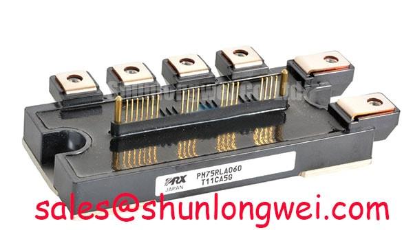
With the DC link discharged and the drive board disconnected, first compare the cold-state terminal relationships of the removed module against the original circuit diagram before fitting PM75RLA060. This Mitsubishi Electric intelligent power module is officially rated at 600 V and 75 A, supplied in a Mitsubishi IPM Module housing. Those ratings define the module identity; they do not by themselves confirm interchangeability with another footprint, gate-drive board, cooling interface, or inverter topology.
For incoming inspection, check the case, terminals, mounting faces, and connector areas for damage that could affect mechanical seating or electrical clearance. A multimeter diode-mode check can help document repeatable junction-direction behavior before installation, but it cannot prove switching performance, protection behavior, or isolation condition under operating voltage. Mitsubishi Electric’s power semiconductor portfolio information provides broader manufacturer context for power-device applications and handling.
💡 Bench Tip: Record cold-state readings with ESD-controlled handling and compare like-for-like terminal paths across the removed and replacement assemblies before applying any gate-drive or DC-link voltage.
| Parameter | Value | Classification |
|---|---|---|
| Product model | PM75RLA060 | Official product identification |
| Manufacturer | Mitsubishi Electric | Official product identification |
| Voltage rating | 600 V | Official Specification |
| Current rating | 75 A | Official Specification |
| Package category | Mitsubishi IPM Module | Official package description |
Before commissioning a PM75RLA060 installation, verify that the inverter power stage, driver outputs, current-sensing path, and thermal interface correspond to the original equipment design. The 600 V and 75 A ratings are official module specifications, while the allowable DC-link operating point, switching frequency, current waveform, heatsink capability, and overload profile remain system-determined conditions.
During a controlled first power-up, it is useful to observe phase-current symmetry, DC-link behavior, heatsink temperature trend, and gate-drive timing together. A thermal imbalance can arise from several sources, including uneven mechanical contact, a degraded fan path, driver-command asymmetry, current-sensor offset, or an abnormal load. It should not be attributed to the IPM alone without measurements from the complete inverter assembly.
The positive temperature coefficient of IGBT conduction behavior is commonly considered when engineers assess steady-state current sharing among parallel semiconductor paths. This is a Design Consideration, not a confirmed PM75RLA060 parallel-operation guarantee. Dynamic current balance still depends heavily on matched gate-loop routing, equalized power-path impedance, coordinated protection response, and switching-node layout. Where a repair involves multiple parallel legs, compare waveform timing and current distribution under the same controlled load conditions rather than relying on a static resistance check.
Physical clearances around DC-link conductors and phase outputs should preserve the original equipment’s insulation and creepage arrangement. Do not reduce terminal spacing to accommodate a substitute busbar or altered cable lug. For commercial string inverter and micro-grid energy-storage equipment, technicians should also inspect pre-charge circuitry, contactor sequencing, braking paths where present, and discharge status before connecting diagnostic instruments.
If a replacement assessment includes a different module family, the linked CM300DXDX1-24A should be evaluated only against the original schematic, mechanical drawing, thermal arrangement, voltage class, current demand, and control method. It is not appropriate to infer direct replacement suitability from a product name or current rating alone.
Transient Dynamics & Electrical Design: Dynamic Power Loss Dissipation and Multi-R on PM75RLA060
A repetitive pulsed-load problem cannot be assessed from the PM75RLA060 nominal current rating alone. Junction temperature responds to pulse energy, duty cycle, switching loss, conduction loss, thermal interface condition, and the time-dependent impedance from junction to case and from case to heatsink. A multi-resistance thermal model is commonly used by system designers because a short high-energy event and a continuous load can produce very different junction-temperature excursions even when average current appears similar.
This is an Engineering Recommendation: use the original manufacturer thermal data and the actual measured electrical waveform to calculate peak junction-temperature margin for the intended load cycle. In practice, engineers combine instantaneous loss estimates with the applicable transient thermal-impedance curve, then verify the result through thermal measurement on the assembled inverter. The PM75RLA060 product identification data provided here does not establish a specific transient thermal-resistance value, maximum junction-temperature limit, or overload duration.
Dead-time control is equally important when investigating a failed inverter leg. A gate command that overlaps its complementary command can create shoot-through; an excessively conservative delay can distort output current and increase loss. The required dead-time buffer must be determined from the installed driver propagation delays, gate discharge behavior, PWM strategy, temperature range, and measured switching waveforms. The right field method is to examine complementary gate signals and the switching node with suitable isolated measurement equipment while confirming that the DC-link voltage remains within the system’s intended boundary.
In energy-storage converters, regeneration or rapid load deceleration can raise the DC-link voltage when energy returns from the AC side or motor side. Braking choppers, braking resistors, battery-management coordination, and inverter protection all belong to the system-level energy-management design. The PM75RLA060 should be assessed as one element in that chain, with measured bus-voltage events reviewed alongside command timing and load behavior.
Where the power stage includes a separate rectifier or auxiliary conversion position, the CM100DY-12E is a related power-module reference for schematic and subsystem comparison. Its electrical and mechanical characteristics must be checked independently before it is considered in any service bill of materials.
Transient Dynamics & Electrical Design: Kelvin Emitter Connection on PM75RLA060
Verify the actual PM75RLA060 terminal assignment from the original equipment documentation before making any assumption about an auxiliary emitter or Kelvin-return connection. The supplied official identification data confirms the model, 600 V rating, 75 A rating, and Mitsubishi IPM Module package category, but it does not confirm an individual auxiliary-emitter pin assignment or internal terminal arrangement.
Where an inverter design does provide a dedicated driver reference return, the design objective is to keep the gate-driver sensing return separate from the high-current power-emitter path. This Design Consideration reduces the influence of common emitter inductance on the measured gate-to-emitter voltage. If a shared high-current return carries a fast switching current, the induced voltage can alter effective gate drive, making a stable bench waveform difficult to reproduce in the installed machine.
For a service inspection, trace the driver return from the control board to the module interface and compare it with the original copper routing. Look for lifted pads, fractured connector solder joints, added wire links, or repair work that has merged a sensitive gate-return path with a phase-current path. Oscillation, unexpected desaturation events, or irregular current sharing can each be associated with several circuit conditions. Confirm the observed behavior using a known-good signal path and appropriately referenced oscilloscope measurements.
Keep gate-drive conductors compact and paired with their intended return conductors to minimize parasitic loop inductance, particularly when suppressing turn-off overshoot and false turn-on behavior. The acceptable arrangement is determined by the complete drive board, DC-link structure, protection circuit, and measured transient margins. Avoid lengthening gate leads simply to make assembly easier unless the revised waveform performance has been validated.
⚠️ Field Alert: Disconnect power, verify stored-energy discharge, and prevent inadvertent gate-drive enable before moving module terminals or probing a power-stage connector.
PM75RLA060 Thermal-Electrical Optimization: High dv/dt Cross-Conduction Shoot-Through Practical Tuning
High switching-node dv/dt can couple through device capacitances and external layout parasitics, potentially raising the gate potential of an inactive switch. In a complementary inverter leg, that disturbance can contribute to cross-conduction if the driver return, turn-off path, interlock behavior, or gate impedance is not controlled. The PM75RLA060 rating of 600 V establishes its official voltage class, while the acceptable switching transient is determined by the specific DC-link arrangement and measured device stress.
A dedicated low-impedance active Miller clamp is often evaluated in gate-driver designs to hold the inactive gate near its emitter reference during high dv/dt events. Negative gate bias is also used in some system architectures, but the appropriate bias, clamp threshold, resistor selection, and driver compatibility must be verified against the original PM75RLA060 drive documentation and measured waveforms. These are Design Considerations, not factory-programmed requirements stated by the available product parameters.
When tuning a repaired drive board, begin with the original gate-drive configuration where documentation is available. Confirm that complementary commands remain interlocked, that the turn-off route is intact, and that the driver isolation barrier is functioning as expected. Optical isolators and digital isolators can be affected by layout, supply decoupling, grounding strategy, and common-mode transient conditions. A clean logic waveform at the controller does not by itself confirm a clean gate waveform at the power module.
Check the module-to-heatsink interface for flat seating, correct hardware engagement, and even pressure across the manufacturer-defined mounting points. Mounting torque, thermal compound thickness, spring hardware, and heatsink flatness should follow the original equipment or module documentation. These mechanical variables influence thermal transfer and can alter the apparent electrical behavior of a power stage during extended loading.
For broader context when reviewing switching-loss mechanisms, gate-loop discipline, and industrial-drive fault analysis, see Unlocking Efficiency in Industrial Drives. For manufacturer-level technology context, Mitsubishi Electric also publishes information on its global semiconductor device technologies. Any final repair release should be based on measured gate signals, phase-current response, DC-link behavior, and thermal stability in the actual equipment.