

Content last revised on October 4, 2026
Benchtop Waveform Tuning: Dynamic Power Loss and Thermal Response
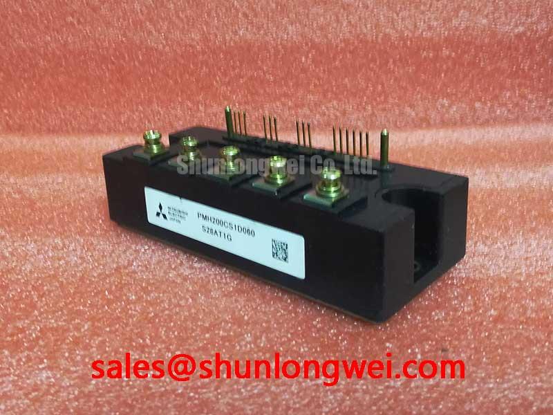
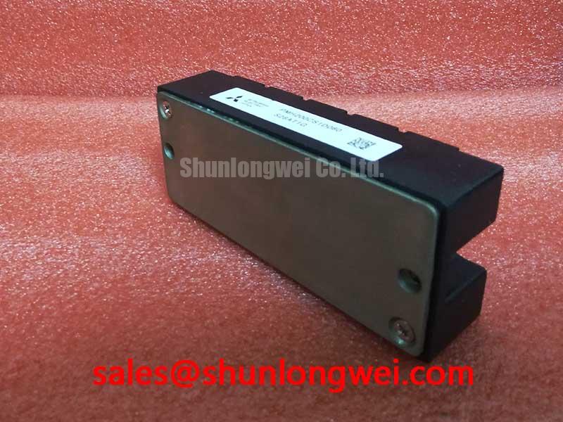
With the equipment isolated and the DC link discharged, check the installed module marking against PMH200CS1D060 before comparing terminal positions, connector orientation and heatsink contact surfaces. Mitsubishi Electric specifies this device as a 600 V, 200 A IPM module (Official Specification). Those ratings establish an initial identification boundary; they do not establish that an existing gate interface, protection circuit or cooling arrangement is compatible.
For a repair assessment, first record the original module’s mounting arrangement and the equipment’s operating conditions. Inspect the heatsink for blocked airflow, uneven contact marks and aged thermal interface material. After installation, compare case temperature and switching waveforms under controlled operating conditions rather than treating a successful cold start as proof of adequate cooling.
The 200 A rating is an Official Specification, not a stated allowance for pulsed overload in this equipment. As a Design Consideration, repeated load pulses can heat the junction faster than the heatsink temperature indicates. A transient thermal calculation would require the applicable manufacturer thermal impedance data, measured pulse duration and a defensible power-loss estimate. Without those inputs, a peak junction-temperature margin for PMH200CS1D060 cannot be calculated reliably.
On the bench, capture current and voltage across the switching interval at representative loads. Compare rising and falling edges with the known-good equipment record, if one exists, and look for changes as the module warms. An altered waveform may reflect the drive circuit, load, DC-link layout or cooling condition; it does not identify a module fault by itself. Engineers evaluating an industrial inverter welder or a medium-frequency induction-heating supply should use the equipment documentation to establish its actual duty cycle before interpreting these measurements.
When assessing a different part, compare more than headline ratings. The linked CM300DXDX1-24A is a separate module to examine during an alternatives review, not a verified direct replacement for this IPM. Package fit, terminal assignment, control functions, thermal behavior and equipment approval all need independent confirmation.
Field Diagnostics & Commissioning: Gate Return Paths in PMH200CS1D060 Topologies
Trace the installed control harness before connecting test equipment. The available product parameters identify an IPM package but do not establish that PMH200CS1D060 exposes a Kelvin emitter terminal. If the equipment schematic shows a dedicated sensing or gate-return path, follow its documented connection and keep it distinct from a high-current return where the original design requires that separation. Do not infer a terminal function from a similar-looking connector.
As a Design Consideration, shared return impedance can allow switching current to disturb the voltage seen by a control circuit. Check the driver reference and switching waveform together, using measurement practices appropriate to the live power stage. Ringing or intermittent trips may warrant inspection of harness routing, connector seating and the DC-link return path. The system engineer should determine acceptable waveforms from the original drive documentation and measured operating conditions; neither a negative gate bias nor a particular switching-frequency range is specified by the supplied product data.
Cooling checks belong in the same commissioning record. Clear dust from the heatsink and air passage, inspect the thermal interface during scheduled maintenance, and compare temperature behavior at the equipment’s documented load settings. High ambient temperature or reduced airflow can narrow operating margin, but a derating figure for this module requires the relevant manufacturer curves and the equipment’s cooling data. For general measurement and failure-analysis context, the Field Engineer’s Handbook can support a structured maintenance record; it does not replace model-specific specifications.
Maintenance note: Isolate and discharge the equipment before reseating the module’s control connector.
Field Diagnostics & Commissioning: Desaturation Detection in PMH200CS1D060 Topologies
Locate the protection circuit on the equipment schematic before assigning a cause to a fault indication. The supplied specifications do not confirm the desaturation threshold, blanking interval, short-circuit withstand time or turn-off sequence of PMH200CS1D060. These settings must not be inferred from the IPM designation. Identify what the installed controller actually monitors, where its fault signal originates and how that signal is latched or cleared.
A Design Consideration for short-circuit protection is that detection and turn-off affect both device stress and DC-link overvoltage. A fast current interruption can produce a substantial voltage transient in an inductive path. Any proposed change to fault timing or turn-off behavior therefore needs validation against the original control design and measured switching waveforms; this page provides no module-specific timing prescription.
During fault investigation, record whether the indication occurs at startup, under load or during shutdown. Compare DC-link voltage, load current and control-supply behavior at the same event. An intermittent fault may be associated with several conditions, including a connector problem, supply disturbance or genuine overcurrent, so the observed sequence matters more than a single alarm label. Mitsubishi Electric’s power semiconductor information provides manufacturer context, while the installed equipment documentation remains the authority for its protection implementation.
Review connected stages as a system rather than treating every Mitsubishi Electric module as interchangeable. For example, CM100DY-12E may appear in a broader power-stage assessment, but its circuit role and suitability must be checked against the actual schematic. A rectifier function, control interface or replacement relationship cannot be assigned from a product name alone.
Preventing Spurious Faults: Busbar Geometry and Switching Overshoot
Inspect the existing busbar and DC-link connections for loose joints, altered routing and signs of localized heating before changing components. As a Design Consideration, reducing switching-loop inductance helps limit turn-off overshoot: the voltage added to the DC-link level rises with loop inductance and the rate at which current changes. That relationship explains why a visually small change in current path can matter, but it does not establish a universal busbar-inductance target or snubber value for PMH200CS1D060.
If the original assembly uses a planar busbar, preserve its intended conductor alignment, insulation and connection sequence during reassembly. Verify clearances against the equipment design rather than applying a generic layout rule to an unknown enclosure. Any proposed snubber or overvoltage-clamping change should be evaluated from measured peak voltage, operating current and component ratings during switching tests. A MOV elsewhere in the supply may address a different transient path and should not be assumed to control overshoot at the module terminals.
Correlate a spurious trip with the voltage waveform at the relevant test points and with the controller’s fault record. If overshoot changes after maintenance, revisit terminal contact, DC-link capacitor connections and measurement probe placement before attributing the result to the IPM. Mitsubishi Electric’s semiconductor device resources offer broader technical context; final limits for this repair must come from applicable module documentation and validation in the actual equipment.