
Content last revised on September 14, 2026
Preventing Spurious Faults: Ensuring Uniform Heatsink Contact Pressure Guidelines for PP15012HS(ABBN)5A
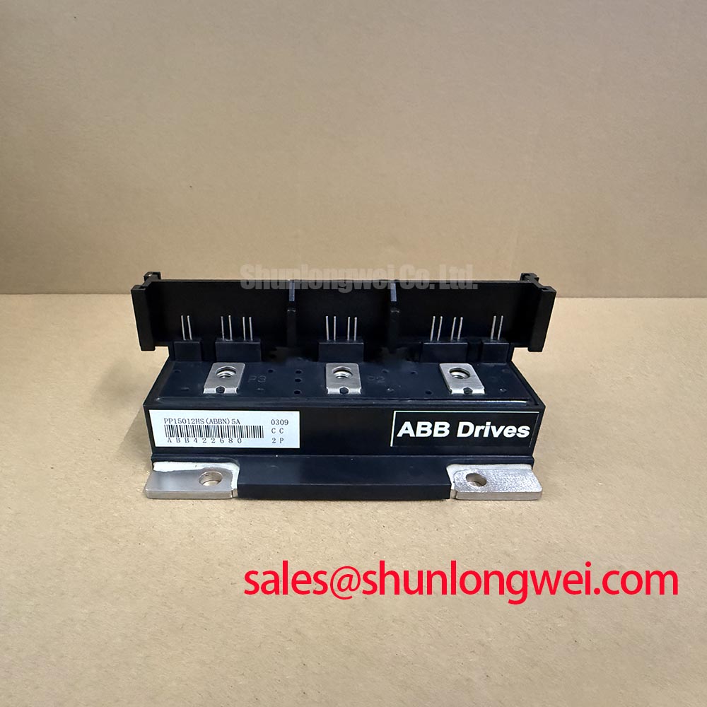
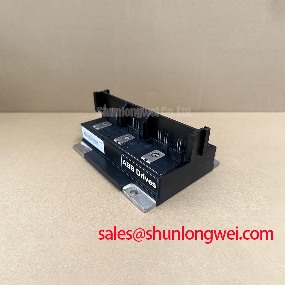
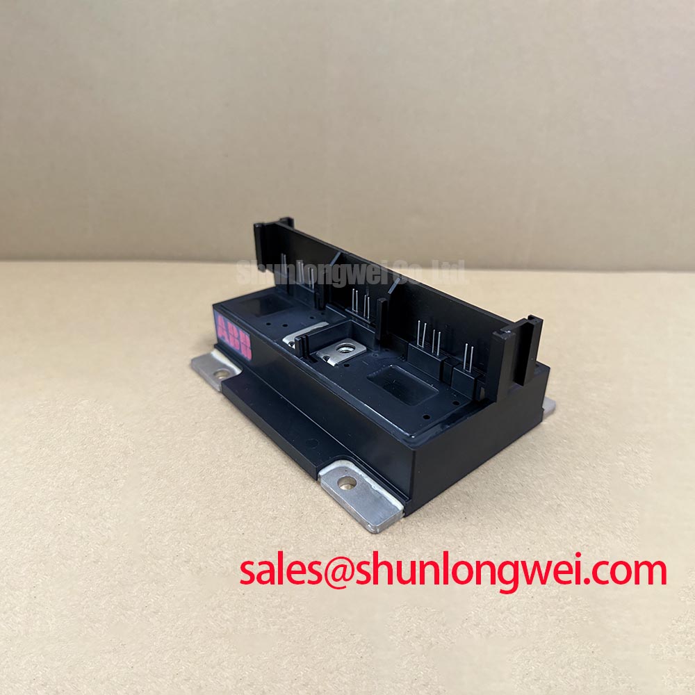
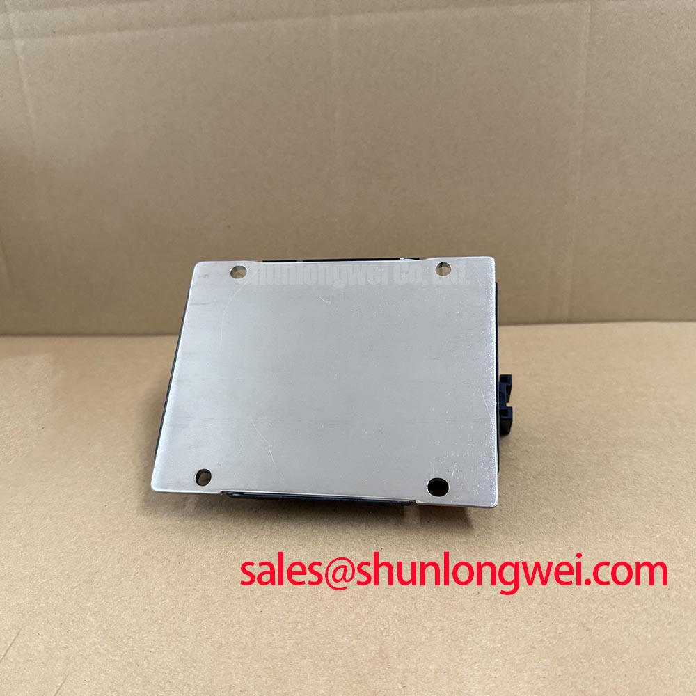
Thermal inspection should start with the mechanical interface rather than with assumptions about semiconductor failure. Remove the module only after the cabinet has been made safe, then inspect the copper baseplate, heatsink mounting surface, fasteners, insulating materials, and terminal hardware. A surface that appears clean can still have uneven contact, excessive compound, or local distortion that raises junction temperature during high current operation.
The supplied product information confirms a continuous collector current rating of 150 A and a repetitive peak current rating of 300 A. These are Official Specification values, not a substitute for a thermal calculation. The applicable data sheet should be used to obtain the specified thermal resistance from junction to case, allowable case temperature, transient current conditions, and any duty cycle limitations. If the required Rth(j-c) value is not available in the purchasing record, it should be confirmed from the original Powerex documentation rather than inferred from a visually similar module.
Apply thermal interface material as a controlled, continuous film that fills microscopic surface irregularities without creating a thick insulating layer. The exact compound type, application thickness, and spreading method should follow the module manufacturer’s mechanical instructions and the equipment service specification. A practical inspection method is to remove a serviced unit after a controlled run and examine the contact pattern on the baseplate. An uneven imprint may indicate surface flatness, fastener sequence, contamination, or mounting pressure variation. The pattern should be treated as diagnostic evidence, not as proof of one single fault mechanism.
Fastener torque is a Design Consideration and must come from the applicable Powerex mechanical specification or the original equipment assembly record. Do not copy a torque value from another package simply because the bolt size looks identical. Tighten progressively and evenly, using calibrated tooling and the specified sequence. Excessive force can deform the module or heatsink; insufficient force can leave thermal voids and allow contact resistance to change during thermal cycling.
Terminal connections require the same discipline. Confirm that busbars sit squarely on the intended terminals, that no cable lug is applying side load, and that conductor strands cannot approach adjacent high voltage nodes. Terminal torque is an assembly requirement, not an electrical rating, so the value and hardware combination must be verified against the original documentation. After commissioning, compare phase terminal temperature under a stable load. A persistent difference between equivalent paths warrants inspection of current sharing, busbar geometry, connection resistance, and cooling airflow.
Fuse coordination must also be reviewed from the actual protective device data. The module’s 1200 V VCES rating and current ratings do not provide an I²t coordination table. The semiconductor fuse manufacturer’s clearing I²t, prospective fault current, fuse voltage rating, and response time should be compared with the equipment short circuit study. A fuse that carries normal current may still be unsuitable for limiting a destructive fault, while an oversized fuse can allow damaging energy before interruption. The final selection is an Engineering Recommendation subject to the system protection study.
⚠️ Maintenance Note: Check heatsink contact condition, fan or coolant path cleanliness, and terminal tightness during scheduled service, then compare operating temperature across equivalent current paths after reassembly.
Field Diagnostics & Commissioning: Minimizing Commutation Turn-Off Voltage Spikes in PP15012HS(ABBN)5A Topologies
For a six pack, begin commissioning by confirming the phase sequence, DC bus polarity, gate channel assignment, and isolation barriers against the original converter schematic. The stated topology is a 3 phase inverter, 6 pack, but the supplied factory parameter set does not define individual terminal names, gate thresholds, internal diode recovery data, or recommended gate resistance. Those details must be taken from the correct Powerex technical document for this exact designation.
Turn-off voltage stress is normally investigated with a properly rated differential probe and a current probe at the switching node. The engineer should capture the collector emitter voltage, load current, gate emitter voltage, and commutation timing together. Minimize parasitic loop inductance as a Design Consideration to reduce inductive overshoot, then verify the measured peak against the actual DC link voltage and the 1200 V VCES boundary during switching tests. A waveform anomaly should not be assigned to the module without checking probe bandwidth, grounding, gate drive isolation, busbar layout, and the opposite switching device.
Reverse recovery behavior is especially important when the commutation path includes an antiparallel diode. The available product parameters do not state Irrm, trr, softness factor, recovered charge, or switching loss. These values should not be estimated from the 150 A continuous current rating. Use the exact data sheet or a controlled laboratory characterization to determine whether the observed current peak is compatible with the design. The result can influence gate timing, snubber selection, switching frequency, and cooling requirements, but those decisions remain system determined.
EMI investigation should separate conducted noise from radiated coupling. Check the gate loop, DC link loop, control cable routing, shield termination, and cabinet bonding while observing the switching waveform. The general principles discussed in Electromagnetic Interference mitigation are relevant to layout and filtering, but a discrete power module cannot independently claim compliance with a complete CISPR or EN 55011 installation limit. Compliance belongs to the finished converter and its installation.
When a high current electrolyzer rectifier shows intermittent overcurrent or gate fault indications, record the event sequence before replacing the module. Inspect the fault log, DC link ramp, phase current balance, gate supply stability, dead time, and switching node overshoot. A repeatable trip may reflect protection threshold interaction, commutation stress, wiring inductance, or thermal conditions. Compare the suspect channel with a known good phase path using the same probe arrangement and load state.
Power semiconductor material studies, including work involving deep level behavior, can be useful in specialist reliability analysis, but the supplied data for this part does not establish a silicon carbide construction or any specific trapping mechanism. The deep level transient spectroscopy reference should therefore be treated as general background rather than evidence of an internal structure for this Powerex module.
Preventing Spurious Faults: AC Line Surge Immunity, Lightning Transients Guidelines for PP15012HS(ABBN)5A
Surge protection should be evaluated at the converter input, not assumed from the module’s isolation rating. The specified 2500 V RMS isolation voltage is an Official Specification for isolation capability under the manufacturer’s stated test conditions; it is not a guarantee of immunity to every lightning or switching transient in an installed cabinet. Designers should map the utility supply, transformer impedance, grounding arrangement, cable length, and external surge environment before selecting protection.
For an AC input stage feeding a high current DC rectifier, inspect the coordination between upstream breakers, semiconductor fuses, line reactors, surge protective devices, and the rectifier switching network. MOV selection is system dependent. Its continuous operating voltage must suit the actual line condition, while its surge energy and clamping behavior must be checked against the anticipated transient. The MOV must not be treated as a universal shield for a device rated at 1200 V VCES.
IEC 61000-4-5 testing can provide a structured method for evaluating surge performance, but the appropriate test level, coupling network, repetition, and pass criteria belong to the finished equipment specification. A module product page cannot certify compliance with that system test. During validation, monitor the module terminals and DC link for abnormal overshoot, inspect protective components after testing, and confirm that the protection circuit returns to a safe state without leaving progressive damage.
RC snubber stages may be considered where switching edge behavior or commutation overshoot requires control. The resistor and capacitor values should be selected from measured waveforms, device switching data, leakage limits, pulse energy, and the actual circuit impedance. The supplied factory parameters do not specify Rs, Cs, dv/dt immunity, or a snubber network. Any proposed network is therefore an Engineering Recommendation that must be validated for heating, repetitive pulse stress, insulation spacing, and interaction with the gate drive.
Maintain adequate creepage and clearance around high voltage terminals, busbars, fuse bodies, and surge components. The required distances depend on working voltage, pollution environment, insulation material group, altitude, and the applicable equipment standard. Do not present the 2500 V RMS isolation rating as a creepage or clearance dimension. Inspect for dust, condensation residue, carbon tracking, and sharp conductor edges during preventive maintenance, especially in installations exposed to humidity changes.
Field Diagnostics & Commissioning: Saturable Reactor and Snubber Sizing to Prevent Localized Stress in PP15012HS(ABBN)5A Topologies
A saturable reactor can be evaluated when the converter requires control of current rise during commutation or fault conditions. Its selection must be based on the actual phase current waveform, pulse duration, core behavior, reset conditions, allowable voltage drop, and thermal duty. The 150 A IC and 300 A ICRM values define supplied current ratings, but they do not specify a reactor value, a permitted di/dt, or a guaranteed short circuit withstand period.
During bench commissioning, capture current at each equivalent phase and examine whether current sharing remains consistent through turn on, conduction, and turn off. Check the busbar joints and reactor connections for localized heating, discoloration, vibration, or mechanical looseness. If a current spike appears, verify the measurement chain and compare the event with gate timing, DC link voltage, fuse condition, and snubber current before changing the reactor.
Snubber sizing should follow the measured energy and switching behavior of the complete commutation loop. A useful Engineering Recommendation is to minimize stray inductance and place the damping network close to the switching path, while allowing the system engineer to determine Rs and Cs through oscilloscope testing and thermal verification. The network must be rated for repetitive pulse voltage and current, and its physical insulation must match the surrounding high voltage environment.
Protection coordination remains central to dead short circuit analysis. Review the semiconductor fuse clearing I²t against the prospective fault current and the converter’s fault detection response. Because no fuse I²t value is included in the supplied product parameters, no precise coordination limit can be assigned to this module. The selected fuse, wiring inductance, current sensor delay, gate inhibit time, and DC source impedance must be evaluated together.
In regenerative braking or bidirectional DC DC battery equipment, energy flow can reverse and thermal cycling can become more demanding than steady rectifier operation. Engineers should verify the switching topology, braking resistor duty, reverse power path, cooling transient, and DC link control sequence. The module’s listed topology is a three phase inverter six pack, while suitability for a particular bidirectional battery charger or regenerative chopper remains subject to the complete circuit design and Powerex application data.
For long term service planning, trend case or heatsink temperature, phase current balance, gate waveform quality, cabinet humidity, and terminal condition. No field failure rate, operating life in hours, or thermal cycle life is stated in the supplied official parameters, so those figures should not be assigned to PP15012HS(ABBN)5A. When the power stage is paired with industrial displays or control interfaces, the system documentation should also define the display subsystem separately; the principles in The Ultimate Guide to Industrial TFT LCD Technology may assist with that broader equipment review.