Content last revised on September 20, 2026
PS11032-Y1 Replacement Assessment
Before fitting PS11032-Y1, isolate the drive, compare the board footprint and terminal assignment with the original service documentation, and inspect the Mini DIPIPM seating area for heat discoloration, cracked solder joints, contamination, or lifted copper pads.
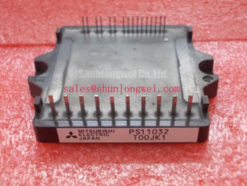
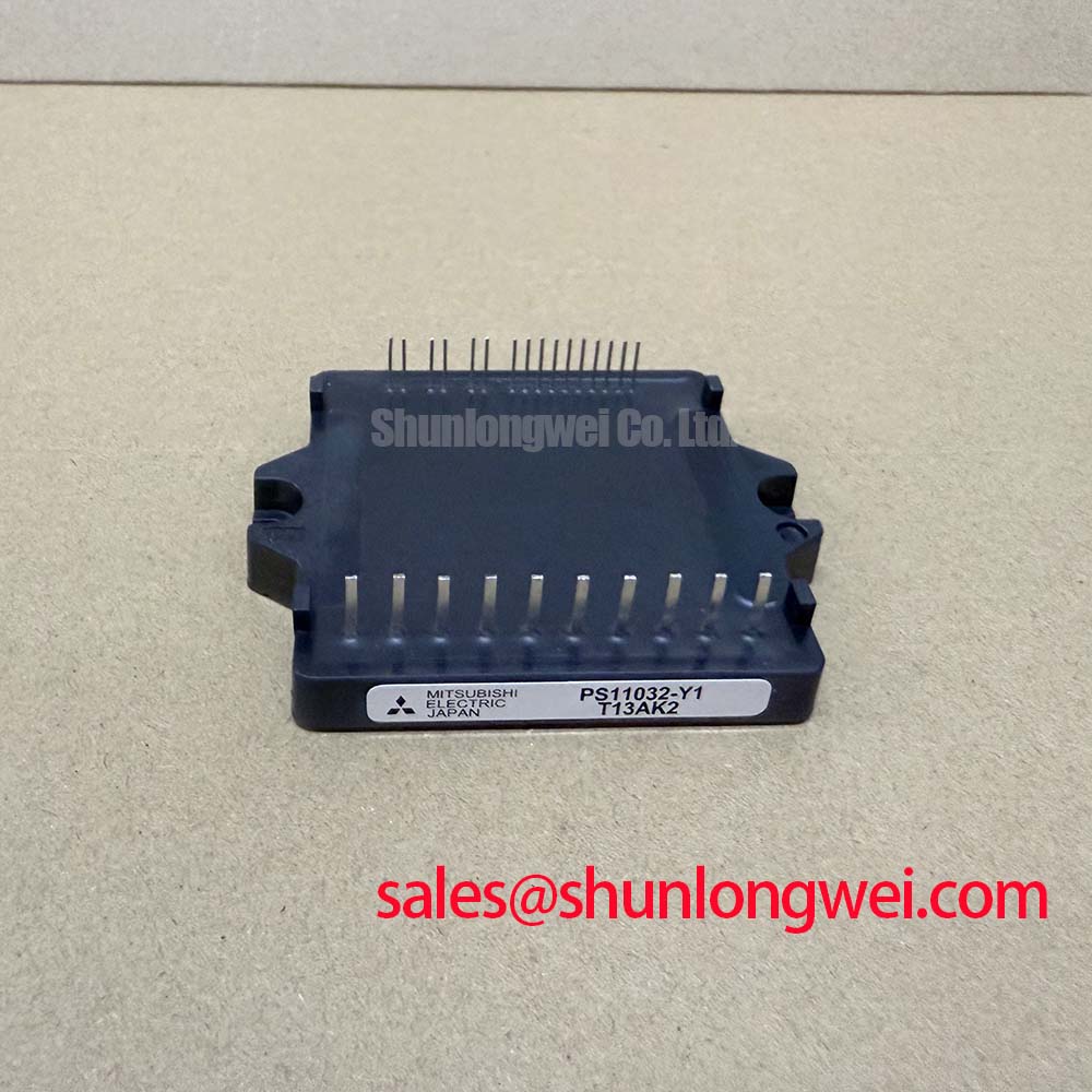
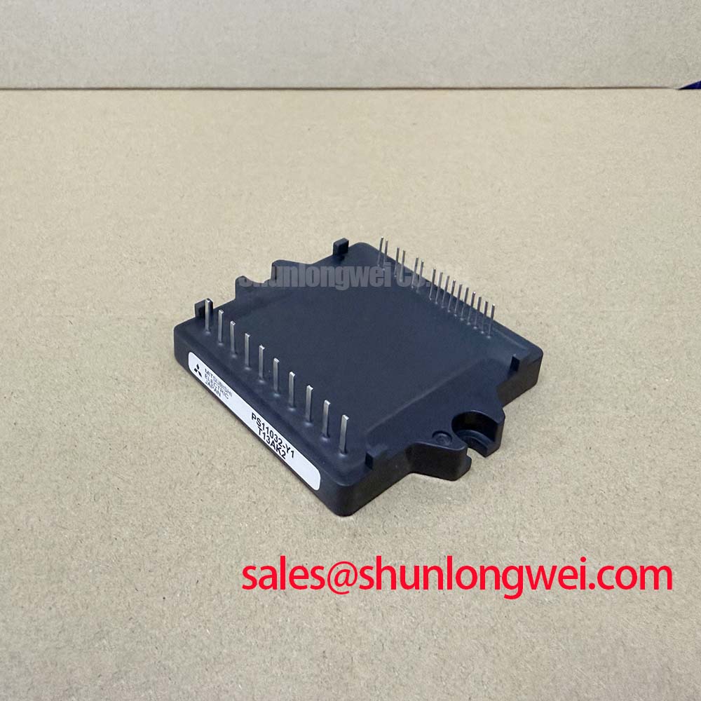
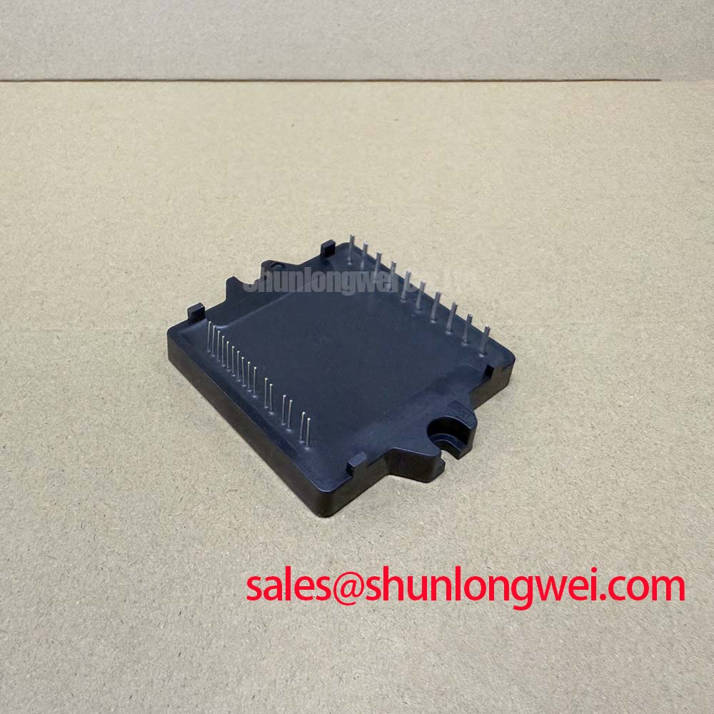
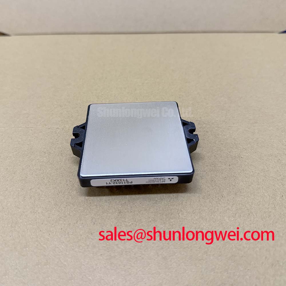
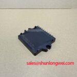
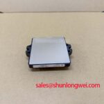
The Mitsubishi Electric PS11032-Y1 is a Mini DIPIPM intelligent power module rated at 1200 V and 15 A under its specified rating conditions. These ratings establish the electrical identity of the replacement unit, but they do not confirm board compatibility, control pin mapping, driver supply requirements, or protection behavior in a particular servo drive. Those items should be checked against the equipment schematic and original module documentation.
| Parameter | Official Specification |
|---|---|
| Manufacturer | Mitsubishi Electric |
| Part number | PS11032-Y1 |
| Module category | Mini DIPIPM intelligent power module |
| Voltage rating | 1200 V |
| Current rating | 15 A |
Assembly Integrity & Layout Architecture for PS11032-Y1
Begin the replacement assessment by tracing the control supply return, power return, command inputs, fault output path, and motor phase routing around PS11032-Y1. A Mini DIPIPM installation depends on the host board to preserve separation between noisy switching conductors and low level control wiring. Design Consideration: the isolated DC DC supply and its insulation barrier belong to the surrounding drive design, not to the published identity of this module. The integrator should verify isolation coordination, transient immunity requirements, and clearance distances against the original equipment safety architecture.
Unexpected gate activity, intermittent fault indications, or unstable motor motion can arise from several locations, including a deteriorated auxiliary supply, contaminated PCB surface, poor return routing, or measurement reference errors. Check the supply waveform and logic reference at the installed board under controlled switching conditions, then compare it with a known good channel where available. Guidance from Mitsubishi Electric power semiconductor resources can help place the module within the broader intelligent power module family, while the original drive documentation remains decisive for pin level integration.
For high dynamics CNC and robotics servo repairs, retain the original separation between power traces and command traces. If the board documentation identifies a dedicated low noise emitter or return connection, route it as documented rather than combining it with a high current phase return. Do not infer the presence of such an auxiliary terminal from package family alone.
Preventing Spurious Faults: Baseplate Thermal Grease Layer Control Guidelines for PS11032-Y1
PS11032-Y1 is identified as a Mini DIPIPM; no external baseplate specification has been provided for this part. Thermal grease thickness, baseplate curvature correction, and heatsink screw torque must therefore not be treated as official PS11032-Y1 requirements. The system integrator should inspect the original cooling interface and follow the host equipment service procedure for the actual module mounting arrangement.
Design Consideration: clean blocked fan paths, dust accumulation, aged interface material, and loose heatsink hardware before concluding that an IPM is responsible for a thermal shutdown. Observe heatsink temperature behavior, fan operation, and the condition of nearby electrolytic capacitors during a controlled run. ⚠️ Maintenance Note: Periodically monitor contact temperature rise and verify that the cooling airflow path remains clear after every major drive service.
Gate source and sink capability, external damping resistance, and ringing control are characteristics of the complete gate drive implementation. Where the original circuit includes external gate network components, retain their intended topology and inspect associated resistors, capacitors, and solder joints. Changing damping values without waveform verification can alter switching stress and fault sensitivity. The Infineon CIPOS IPM reference material offers useful industry context on integrated power modules, but does not define PS11032-Y1 specifications.
PS11032-Y1 Circuit Protection & Reliability: Calibrating DC Link Capacitance Bank Layout and Low ESR
At turn off, voltage overshoot is influenced by DC link voltage, switching current change, and stray inductance in the commutation loop. Engineering Recommendation: keep the capacitor connection and power loop compact and symmetric where the existing drive layout permits, then verify peak voltage at the module terminals during switching tests. A low inductance bus arrangement helps reduce the overshoot component created when loop inductance interacts with current slew rate.
Inspect capacitor terminals, laminated bus connections, phase output joints, and DC link solder lands for looseness or heat damage. A poor connection can create localized heating and unstable waveforms without presenting a single obvious failure signature. Long motor cables deserve separate attention because transmission line reflections can increase voltage stress at the motor end; evaluate cable routing, output filtering provisions, and measured waveforms according to the original servo drive design.
For repair comparison, 7MBR15SA120 is a separate Mitsubishi power module listing that can be reviewed against the equipment requirements. It should not be assumed to be a physical, electrical, or control compatible replacement for PS11032-Y1 without a documented engineering comparison.
PS11032-Y1 Circuit Protection & Reliability: Fault-Clearing Dynamics and Desaturation
Do not assume that a specific desaturation method, short circuit detection interval, or soft turn off profile is built into PS11032-Y1 unless confirmed by the applicable Mitsubishi Electric documentation. Intelligent power module protection behavior is dependent on the module version and the surrounding controller implementation. During fault investigation, verify controller fault records, command inhibition, supply stability, phase continuity, and the timing relationship between a fault indication and PWM removal.
Design Consideration: a fault clearing path should avoid uncontrolled inductive energy release while stopping current promptly enough for the system limits. Oscilloscope testing should use an appropriate reference method and should compare measured peak margins against the DC link voltage under the actual switching condition. For practical review of gate loop discipline, switching measurement, and protection coordination, consult Precision Gate Drive Design alongside the original drive schematic.