Content last revised on September 17, 2026
PS11032 Intake Inspection and Official Specifications
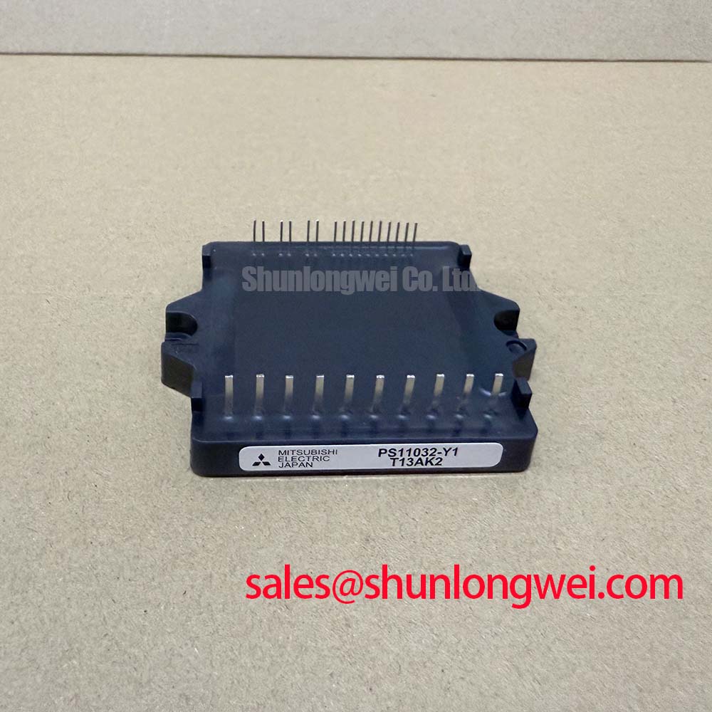
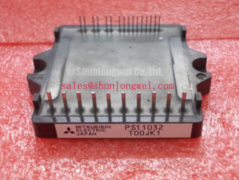
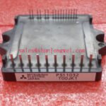
With all power removed and the DC link discharged, begin PS11032 intake inspection by checking the package marking against the service record, then compare terminal-to-terminal diode-mode readings with a known-good drive assembly where available. The PS11032 is a Mitsubishi Electric DIPIPM intelligent power module specified at 600 V collector-emitter voltage, 4 A collector current under specified conditions, 2500 Vrms isolation voltage, 2.1 V typical VCE(sat), and a 15 V nominal control supply. These are Official Datasheet Specifications and define the electrical boundary that must be verified before a repair board is returned to service.
| Official specification | PS11032 value | Integration relevance |
|---|---|---|
| Collector-emitter voltage, VCES | 600 V | Provides a voltage rating for evaluating rectified 220 V and 240 V AC supply architectures, subject to transient and operating-condition checks. |
| Collector current, IC | 4 A under specified conditions | Provides a reference for power-stage current assessment; actual continuous application current depends on thermal and operating conditions. |
| Isolation voltage, VISO | 2500 Vrms | Specifies the module's isolation withstand rating between the power section and the control logic boundary. |
| Typical collector-emitter saturation voltage, VCE(sat) | 2.1 V | Relevant when estimating conduction loss in the on-state under the specified test conditions. |
| Control supply voltage, VD | 15 V nominal | Provides the nominal supply level for the integrated gate-drive logic; the permitted supply range must be checked in the device documentation. |
Benchtop Waveform Tuning: Mitigating Stress via High-Frequency Common-Mode Bearing Current on PS11032
Before reconnecting a motor, confirm that the drive board supplies the PS11032 at its official 15 V VD control-supply requirement and that the DC-link operating condition remains compatible with its official 600 V VCES rating. For a precision stepper or BLDC servo motion actuator, the initial powered check should use isolated differential voltage probing at the module output and a current probe on a motor phase. This lets the technician compare phase switching behavior with the original service waveform or a known-good channel without assuming that a visible waveform irregularity has one cause.
Long motor cables can behave as transmission lines at fast PWM edges. A mismatch between cable impedance, motor impedance, and output impedance can reflect energy back toward the module terminals. Under unfavorable conditions, the reflected step can produce substantial overshoot and, in some cases, approach twice the incident step amplitude at the remote cable end. This is a Design Consideration, not an official PS11032 transient-voltage guarantee. Measure at both the module-side and motor-side connection where the setup permits, because a trace taken at only one point may hide the relevant ringing pattern.
When common-mode current is suspected, inspect the cable shield termination, motor frame bonding, encoder routing, and physical separation between motor conductors and low-level command wiring. An output filter or common-mode choke can be evaluated to reduce conducted stress, but its selection must be determined by the motor cable, switching waveform, control-loop response, and measured peak voltage. Designers should verify voltage peaks against the DC-link condition during switching tests rather than applying a universal filter value.
Bench Tip: Keep the motor cable disconnected until the discharged DC link, PS11032 terminal readings, and control-supply polarity have been compared with the documented repair baseline.
For bootstrap-related checks, the control circuit must follow the drive-board design and the module documentation rather than a generic wiring assumption. Mitsubishi Electric’s DIPIPM bootstrap circuit design note provides useful reference material for examining bootstrap supply behavior, capacitor recharge conditions, and low-side switching dependencies in integrated power-module circuits.
Field Diagnostics & Commissioning: Junction-to-Case Thermal Network Simulation in PS11032 Topologies
During commissioning, record case temperature and output current under the actual actuator duty cycle, then correlate those observations with the PS11032 operating conditions. The official 4 A IC rating under specified conditions and typical 2.1 V VCE(sat) value are useful starting inputs for conduction-loss assessment, but they do not by themselves establish junction temperature during PWM operation. Switching losses, modulation method, ambient conditions, heat-sink performance, and duty cycle remain system-determined variables.
A junction-to-case transient calculation requires the manufacturer’s thermal-impedance data and the applied loss profile. Where the qualified thermal network is available from the original equipment documentation, engineers can apply the pulsed loss history through its multi-RC model and compare the calculated junction result against the permitted operating boundary. Where those data are unavailable, do not create a numerical junction-temperature estimate from case temperature alone. Use measured case trends as a diagnostic indicator and investigate airflow, interface contact, loading waveform, and heatsink condition.
Repeated thermal protection events, unstable output current, or a case temperature trend that differs from a comparable healthy axis can each indicate several possible issues. Check DC-link ripple, commanded acceleration profile, motor winding condition, heat-sink contact, and phase waveform symmetry before attributing the observation to the module. This approach supports repair decisions without inventing field-life figures or failure-rate claims.
Parallel power-module arrangements require particular restraint. The temperature dependence of VCE(sat) can influence current sharing, yet static sharing does not demonstrate dynamic sharing during switching. As a Design Consideration, maintain symmetrical busbar paths, comparable cooling conditions, and matched gate-drive topology, then verify current balance with suitable instrumentation. The PS11032 should only be used in a parallel arrangement after the original system design and validation requirements have been reviewed.
For broader context on power-device efficiency tradeoffs and switching behavior, see Mitsubishi Electric’s power semiconductors and ICs information. That material is useful for technology background, while the PS11032 installation decision must remain tied to its own official specifications and the host equipment’s documentation.
PS11032 Operational Boundaries: Evaluating Baseplate Convexity Compensation and Screw Limits
Inspect the mounting face, heatsink flatness, residue, and previous thermal-interface condition before installing a PS11032. A clean mating surface and a uniform thermal interface reduce local contact resistance that can distort the case-temperature result used during commissioning. The thermal-interface material and its thickness are Design Considerations for controlled mounting processes, not an official PS11032 thickness requirement. The final interface material and thickness must be validated against the module package and equipment assembly specification.
Baseplate curvature, heatsink flatness, and screw sequence all affect contact pressure. Apply fastening in a progressive cross pattern so the module is seated evenly rather than pulled down at one corner. The appropriate screw size, torque limit, washer arrangement, and sequence must come from the original equipment documentation or the applicable Mitsubishi Electric package drawing. Do not infer these values from another DIPIPM package with a similar electrical rating.
After mechanical installation, repeat the cold-state electrical checks before applying the 15 V control supply. Confirm that connector seating, creepage clearances on the repair board, and separation of power conductors from logic traces have not changed during reassembly. The official 2500 Vrms VISO rating is a module isolation withstand rating; it does not certify the finished drive assembly, enclosure, cable system, or machine for any system-level EMC or safety standard.
For a compatible repair assessment involving a different module family, the linked 7MBR15SA120 can be reviewed as a separate engineering reference. Pin arrangement, control architecture, package dimensions, protection behavior, thermal interface, and ratings must be checked independently; electrical category similarity does not establish interchangeability.
Benchtop Waveform Tuning: Mitigating Stress via Planar Symmetrical Busbar Geometry on PS11032
At the DC-link connection, examine the physical current loop formed by the capacitor, busbar, PS11032 power terminals, and return path. Turn-off overshoot follows the relationship between parasitic loop inductance and current-change rate, commonly expressed in engineering analysis as peak voltage rising with DC-link voltage plus inductance multiplied by di/dt. This is an Engineering Calculation principle, but a meaningful peak prediction needs measured or validated loop inductance and switching-current data from the actual assembly.
Planar, closely coupled outgoing and return conductors can reduce loop inductance and improve symmetry between phases. This is a Design Consideration intended to suppress turn-off inductive overshoot, not a stated PS11032 package requirement. Keep DC-link capacitor connections physically close to the power loop where the equipment layout permits, avoid unnecessary conductor area, and verify the resulting peak voltage with differential probing under representative switching conditions.
Snubber capacitors may be evaluated when measurements show excessive ringing, but their value, voltage capability, layout, dissipation, and interaction with the existing DC-link network are system-determined. A capacitor placed remotely can be less effective than expected because its connection inductance becomes part of the transient loop. Check whether changes improve the terminal waveform without introducing unacceptable current, heat, or control effects elsewhere in the actuator drive.
In systems where the PS11032 is part of a larger power chain, the 7MBR15NE120-01 may be reviewed as a separate topology-related power-module reference. Its use, if any, requires independent verification of the converter role, electrical ratings, terminal arrangement, protection coordination, and control interface. For additional engineering background on industrial-drive switching efficiency, consult Unlocking Efficiency in Industrial Drives.