
Content last revised on September 21, 2026
Preventing Spurious Faults: Regenerative DC-Bus Voltage Surge Dissipation Guidelines for PS12036
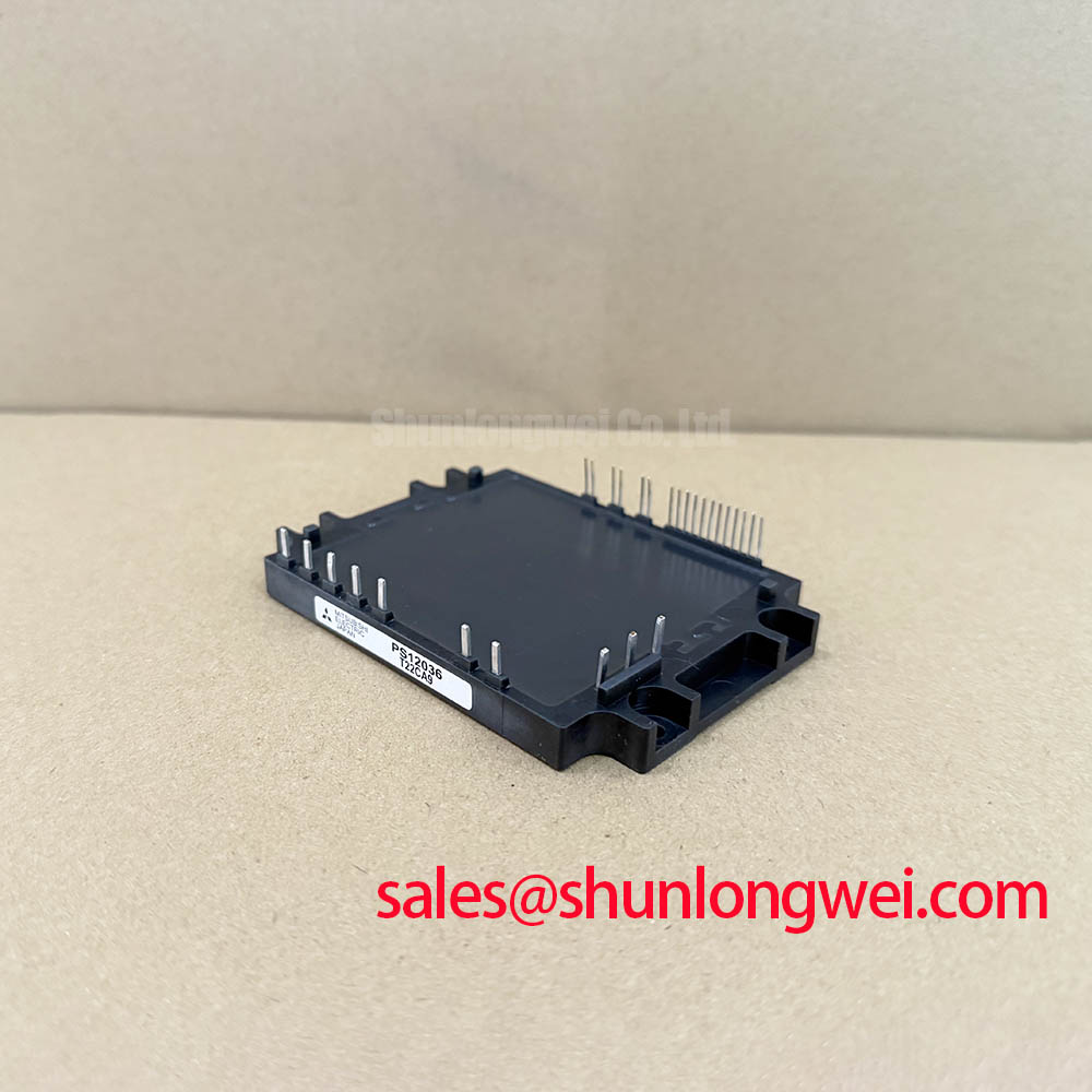
Start regenerative-braking checks at the measured DC bus rather than at the fault indication alone. A traction motor becomes a generator during deceleration, and its recovered kinetic energy is returned to the DC link. If the system does not have a valid path to absorb or return that energy, the bus voltage can rise until the controller enters protection or the power stage is exposed to excessive switching stress. For a drive using PS12036, the 1200 V VCES rating is an Official Specification, not a target bus-voltage setting. The drive designer must verify transient peak margins against the actual DC-link voltage during switching tests.
The braking chopper, braking transistor, and ballast resistor belong to the surrounding drive system unless their presence is specifically confirmed in the original equipment documentation. Their sizing must be based on the moving mass, commanded deceleration profile, motor operating state, available resistor thermal capacity, and control strategy. A resistor that is electrically continuous can still be unsuitable if its thermal installation, cabling, or protection path has changed. Inspect its terminals, enclosure ventilation path, thermal cutout circuit where fitted, and the wiring between the DC bus and braking path before attributing an overvoltage trip to PS12036.
Design Consideration: keep the high-current DC-link loop physically compact and use a busbar arrangement that minimizes loop area. This reduces parasitic inductance that contributes to turn-off overshoot when current changes rapidly. The effectiveness of any busbar arrangement must be established from the system's switching waveform measurements, not assumed from mechanical appearance. Check both the normal motoring transition and the regenerative transition because their current paths and control states can differ.
When a unit trips only during fast deceleration, record the DC-bus waveform, braking-command state, motor speed, load condition, and protection timing on the same test sequence. A rising bus waveform can point toward insufficient energy absorption, a delayed brake command, a discontinuous resistor circuit, or an interaction between current control and speed control. It does not establish one cause by itself. Compare the captured events with a known-good drive under equivalent operating conditions whenever possible.
For a same-voltage-class comparison during an engineering review, 7MBR15PE120 can be examined as a separate IGBT module reference. Package construction, internal circuit arrangement, protection behavior, mounting interface, and driver requirements must be verified independently before any compatibility decision. A matching voltage figure alone does not demonstrate interchangeability.
Field Alert: Disconnect and verify discharge of the DC link before moving busbar or braking-resistor conductors, because stored energy can remain after the controller display is off.
PS12036 Operational Boundaries: Evaluating Thermal Capacitance vs Heat Sink Limits
Thermal assessment should begin with the actual duty cycle, not the average motor current printed on a machine label. The 15 A IO figure is an Official Specification for PS12036, but a short overload, a regenerative event, and a steady motoring period create different junction-temperature trajectories. During pulsed operation, the junction temperature responds through the module's transient thermal impedance rather than through a simple steady-state thermal resistance. The original Mitsubishi Electric documentation should be used to obtain the applicable transient thermal curves and the specified junction-temperature limit.
Engineering Calculation may use the approved transient thermal model from the relevant manufacturer data to estimate the temperature rise produced by each loss pulse. In practical terms, the loss energy during a switching and conduction interval is related to the duration of that interval and the electrical conditions, while the thermal response depends on the corresponding transient impedance at that time. The calculated result must be checked against measured case temperature, heatsink behavior, switching conditions, and the complete operating cycle. A calculation based on an assumed thermal curve or assumed device loss is not an Official Specification for this model.
Heatsink contact condition is frequently as important as heatsink size. Remove only enough interface material to clean the mating surfaces, inspect for flatness and mechanical damage, then apply the thermal interface method specified by the equipment maker. Uneven clamping can create local thermal resistance and can also distort the mechanical reference of a power-module installation. The approved mounting hardware, tightening sequence, and torque must come from the module or equipment documentation. General mounting practices cannot be substituted for a model-specific mechanical requirement.
Where a drive architecture uses parallel power paths, static current distribution deserves separate verification. IGBT conduction behavior can exhibit a positive temperature coefficient over relevant operating regions, which can assist sharing under controlled conditions, but it does not eliminate the need for symmetric electrical and thermal paths. Design Consideration: route equivalent parallel paths with matched busbar geometry, equivalent connection resistance, comparable cooling conditions, and synchronized gate-drive behavior. The system engineer should validate sharing with current measurements across the intended temperature and load range.
A thermal fault that appears after a repeatable work cycle may involve obstructed cooling, deteriorated interface contact, fan control, heatsink contamination, abnormal switching loss, current imbalance, or a changed application load. Inspecting the module in isolation cannot distinguish these conditions reliably. Record heatsink temperature, ambient conditions, motor current, DC-bus voltage, and switching-command behavior while recreating the condition under controlled safeguards.
For system-level context on how IGBTs are evaluated across industrial energy-conversion duties, see Industrial Applications. That reference supports broader engineering discussion; the applicable operating boundary for PS12036 remains the official product documentation and the tested conditions of the installed equipment.
Field Diagnostics & Commissioning: Dynamic Gate Impedance Control for Robust PS12036 Topologies
During commissioning, examine gate-emitter behavior at the module interface with an appropriately rated differential measurement method and a measurement setup suited to the switching environment. The 5 V CMOS/TTL designation is an Official Specification for the logic input interface. It does not define the complete gate-drive waveform, isolation arrangement, gate resistor selection, driver supply arrangement, or protection threshold for a particular inverter board. Those details must be confirmed from the original drive design and applicable PS12036 documentation.
High switching-voltage transition rates can couple through parasitic capacitances and shared return inductance, creating a false turn-on tendency in an inactive switch position. The consequence can include cross-conduction, distorted current waveforms, protection trips, or erratic operation that only appears at a specific bus voltage or load. An active Miller clamp or a controlled negative gate-bias strategy may be considered by the system designer where the original drive architecture supports it. This is a Design Consideration, not an instruction to alter a functioning controller without waveform verification.
Gate impedance controls the tradeoff between switching speed, loss, voltage overshoot, electromagnetic behavior, and immunity to unintended turn-on. A lower impedance can change switching transitions, while a higher impedance can slow them; neither direction is universally correct. The appropriate setting is system-determined and should be validated with double-pulse or representative inverter tests, using the installed DC-link configuration, power cables, motor, and controller timing. Verify peak electrical conditions against the 1200 V inverter voltage rating during those tests.
Pro Tip: Keep each gate-drive return path tightly associated with its drive path and verify turn-off behavior at the module terminals, because a clean waveform at a remote controller test point can conceal inductive error in the power-stage interconnect.
For three-phase modulation context, the external reference Space Vector Modulation in Three-Phase Motor Inverters describes the switching-state framework used in many inverter control systems. The modulation method does not establish PS12036 gate-drive values or fault settings. Those must remain aligned with the controller design, the module documentation, and measured switching results.
If a drive shows intermittent gate-related faults, compare command logic, isolated-driver output, gate waveform, phase current, and DC-bus voltage in time order. A mismatch may indicate noise coupling, supply disturbance, timing variation, an interconnect issue, protection action, or control-board behavior. Capturing correlated waveforms is more defensible than replacing a gate component based on a single fault code.
Field Diagnostics & Commissioning: Isolated DC-DC Power Supply Sizing for Use in PS12036 Topologies
Verify the driver power supply at the isolated driver output while the inverter is switching under controlled load. The supply must deliver the energy required by the installed driver circuit and retain the isolation performance required by the complete equipment design. PS12036's listed 5 V CMOS/TTL logic compatibility does not disclose the isolated DC-DC converter specification, isolation barrier class, common-mode transient immunity, or driver-side supply requirements. The system integrator should verify these values from the original inverter documentation.
Design Consideration: select and validate isolation parts according to the equipment's working voltage, transient environment, safety architecture, creepage and clearance requirements, and controller topology. A stated isolation voltage or transient-immunity value for an auxiliary converter cannot be inferred from the PS12036 rating. Likewise, a module cannot independently claim equipment-level EMC or safety compliance; those outcomes depend on the completed drive, enclosure, cabling, filter arrangement, grounding, and validation method.
In service work, inspect the isolated supply rails both unloaded and during the event that produces the fault. A rail that appears stable with no switching activity can behave differently when common-mode voltage transitions, output current demand, or bootstrap-related activity occurs. Check isolation transformer connections, supply decoupling condition, driver enable logic, fault-reset sequencing, and the physical separation of noisy power conductors from low-level controller routing. Any change should be followed by controlled functional testing before returning equipment to duty.
The converter section's 1600 V VRRM Official Specification is relevant when reviewing the AC-to-DC rectifier function integrated with the module. It should not be used to infer auxiliary-supply isolation capability or line-side protection coordination. For an inverter repair, retain a clear boundary between the rectifier power path, DC-link network, isolated control power, and low-voltage logic interface. This makes it easier to determine whether a recurring event originates in the input supply, energy storage, braking path, controller, or inverter switching stage.
When evaluating a PS12036 installation for forklift low-voltage traction or another industrial motor-drive role, confirm the original equipment's DC-link level, motor current profile, cooling arrangement, control-board interface, protection sequence, and mechanical mounting details as a connected system. The official module ratings establish essential boundaries, while the final integration decision depends on documented compatibility and measured behavior in the intended equipment.