
Content last revised on September 10, 2026
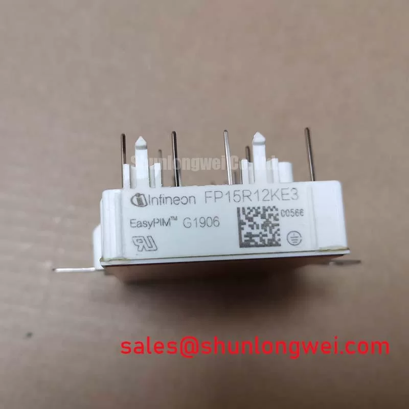
FP15R12KE3G Infineon IGBT Module
The FP15R12KE3G, manufactured by Infineon Technologies, is a high-performance EconoPIM™2 power integrated module integrating a three-phase input rectifier, a brake chopper, a three-phase inverter stage, and an NTC thermistor. Designed with TRENCHSTOP™ IGBT3 and Emitter Controlled 3 diode technologies, this compact module offers an optimized footprint for low stray inductance and enhanced thermal cycling performance. It is an industry-standard choice for low-to-medium power industrial drive systems and inverter designs requiring high power density.
Key Parameter Overview
Decoding the Specs for Enhanced Thermal and Electrical Reliability
Understanding the primary operating parameters of the FP15R12KE3G is crucial for ensuring the module operates within its Safe Operating Area (SOA). Below is the structured breakdown of the module's key technical ratings as specified in the official datasheet:
| Stage / Component | Technical Specification Parameter | Absolute Max / Typical Value |
|---|---|---|
| IGBT (Inverter Stage) | Collector-Emitter Voltage (VCES) | 1200V |
| Continuous DC Collector Current (IC) at TC = 80°C | 15A | |
| Collector-Emitter Saturation Voltage (VCE(sat)) at Tvj = 125°C | 2.00V (typical) | |
| Diode (Inverter Stage) | Repetitive Peak Reverse Voltage (VRRM) | 1200V |
| Continuous DC Forward Current (IF) | 15A | |
| Rectifier Bridge | Repetitive Peak Reverse Voltage (VRRM) | 1600V |
| Maximum RMS Current at Rectifier Output (IRMSmax) at TC = 80°C | 60A | |
| Surge Forward Current (IFSM) at Tvj = 150°C (10 ms pulse) | 260A | |
| Thermal Characteristics | IGBT Thermal Resistance, Junction-to-Case (RthJC) | 1.20 K/W (per IGBT) |
| Diode Thermal Resistance, Junction-to-Case (RthJC) | 2.00 K/W (per Diode) |
Download the FP15R12KE3G datasheet for detailed specifications and performance curves.
Application Scenarios & Value
Achieving System-Level Benefits in Industrial Power Conversion
Engineers often face critical thermal dissipation and space constraints when designing compact motor controllers. The integrated architecture of the FP15R12KE3G resolves these challenges by combining the input rectifier, brake chopper, and inverter stages into a single EconoPIM™2 housing, drastically reducing PCB layout complexity and stray inductance. For instance, in a standard Variable Frequency Drive (VFD) application, the high rectifier surge current capability of 260A ensures the module safely withstands initial motor startup inrush current surges without triggering overcurrent protection or causing device degradation.
Additionally, the integrated NTC temperature sensor provides real-time thermal monitoring directly at the module substrate. This allows control algorithms to adjust switching frequencies dynamically during localized overload conditions, protecting the silicon junction from thermal runaway. For design topologies requiring higher current capabilities within a similar voltage range, the related FP25R12KE3 offers a 25A rating to extend thermal headroom in higher-capacity motor drives.
This module is highly suited for a variety of power electronics systems, including:
- Low-power industrial motor drives and Servo Drives
- Auxiliary power supplies in industrial automation environments
- Low-power Solar Inverter systems and grid-tied converters
Technical & Design Deep Dive
Thermal Resistance and Switching Losses in Modern Power Stages
The performance of the FP15R12KE3G is heavily dictated by its thermal characteristics and switching loss profiles. The junction-to-case thermal resistance (RthJC) of 1.20 K/W for each inverter IGBT acts as a bottleneck for heat transfer from the silicon die to the module baseplate. Think of RthJC as a narrow thermal highway: a lower value allows thermal energy to flow more freely, preventing localized hot spots. By utilizing an optimized thermal grease with a conductivity of λ = 1 W/(m·K), the case-to-heatsink resistance (RthCH) is kept at a low 0.385 K/W per IGBT, facilitating efficient thermal transfer to the external cooling system.
From an electrical perspective, the module exhibits a turn-on energy loss (Eon) of 2.10 mJ and a turn-off energy loss (Eoff) of 1.50 mJ under typical inductive load switching conditions at Tvj = 125°C (with VCC = 600V, IC = 15A, and RG = 75 Ω). High switching losses directly translate to excess heat generation inside the package, limiting the maximum operating frequency. Designers must carefully select the gate resistor (RG) to balance the trade-off between switching losses (Eon/Eoff) and electromagnetic interference (EMI) caused by rapid dV/dt transitions.
Frequently Asked Questions
Engineering and Design Queries Answered
What is the maximum operating junction temperature under switching conditions for the FP15R12KE3G?
The module is qualified for continuous operation under switching conditions up to a maximum junction temperature (Tvj op) of 125°C, with absolute maximum ratings extending to 150°C for transient overload protection.
How does the VCE(sat) of 2.00V at 125°C affect overall inverter conduction losses?
A typical saturation voltage (VCE(sat)) of 2.00V under hot operating conditions (Tvj = 125°C) determines the steady-state conduction loss when the IGBT is fully turned on. Conduction losses can be calculated by multiplying this saturation voltage by the operating collector current, making the FP15R12KE3G highly efficient at nominal currents.
Can the FP15R12KE3G withstand a direct short-circuit event?
Yes, the module has a designated short-circuit withstand time (tP) of up to 10 μs when operating under a gate-emitter voltage (VGE) of ≤ 15V and a DC link voltage (VCC) of 900V at Tvj = 125°C. This allows gate drivers sufficient time to detect desaturation and safely shut down the module before catastrophic thermal failure occurs.