Content last revised on September 19, 2026
SKYPER 42 R Circuit Protection & Reliability: Calibrating Junction to Case Thermal Network Simulation
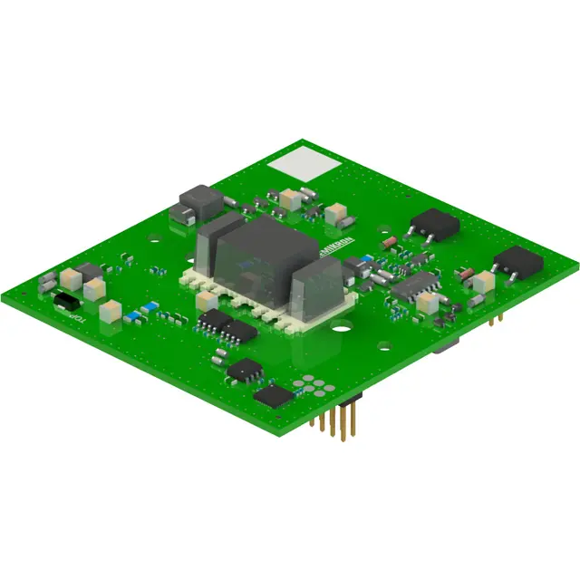
Begin by checking the equipment bill of materials, enclosure marking, terminal arrangement, and installed mechanical footprint before assigning electrical limits to a replacement position. The supplied product data identifies SKYPER 42 R as a Semikron gate-driver unit listed with a 1700 V voltage value, 30 A current value, and Semitrans housing. These are listed product-record values, not automatically collector-voltage or collector-current ratings for an attached IGBT. They define an important starting boundary for repair evaluation, but they do not replace verification of the original converter schematic, driver interface, cooling path, switching frequency, or protection thresholds.
For a junction-to-case thermal simulation of the attached power semiconductor, the system engineer needs the original device thermal impedance curves, switching loss information, conduction loss data, and the actual heatsink interface condition. Those values are not included in the available product data for SKYPER 42 R, so a multi RC thermal network cannot be calculated responsibly from the stated voltage, current, and housing information alone. Treat any thermal model created from the installed assembly as an Engineering Calculation, with each resistance and thermal capacitance traceable to the original component documentation or measured system data.
A practical method is to capture the load profile that precedes a trip, then compare it with case temperature trends, coolant or airflow condition, and switching waveforms. Heavy pulsed operation can create repeated junction temperature excursions even where a heatsink appears stable. The important diagnostic question is whether the thermal stress is linked to changing load duty, impaired heat transfer, uneven clamping, or increased switching energy caused by a disturbed gate drive path. A case temperature reading alone cannot establish the semiconductor junction temperature.
The installed Semitrans driver and power-module arrangement should be inspected for flat, clean mating surfaces, even hardware loading, and evidence that the thermal interface material has been applied consistently. Thermal compound thickness, mounting force, and hardware sequence are Design Considerations determined by the module documentation and equipment mechanical design. A damaged or distorted heatsink surface can increase thermal resistance and create unequal loading across a power assembly even when electrical measurements appear acceptable.
🔧 Bench Diagnostic: Isolate stored DC link energy and confirm the safe discharge condition before disconnecting gate or power wiring for measurement.
| Item | Available Product Record | Integration Meaning |
|---|---|---|
| Product | SKYPER 42 R | Confirm against the original equipment documentation and installed connection arrangement. |
| Manufacturer | Semikron | Use the original manufacturer documentation when validating pin functions and protection behavior. |
| Listed voltage value | 1700 V | Listed value for the product record; do not treat it as the operating voltage rating of an attached power semiconductor without confirmation. |
| Listed current value | 30 A | Listed value for the product record; do not treat it as the collector-current rating of an attached power semiconductor without confirmation. |
| Housing | Semitrans | Verify mechanical fit, terminal orientation, and cooling interface in the actual assembly. |
Protection coordination also requires the DC link, snubber network, MOV selection, control timing, and fault response to be checked as one system. An MOV may limit selected surge events, but it is not a substitute for controlling switching loop inductance or for verifying turn off overshoot under the actual current path. Design Consideration: keep the commutation path compact and mechanically repeatable to reduce parasitic inductance, then verify peak voltage margin against the DC link voltage using appropriately rated switching tests.
For broader manufacturer context, engineers can consult the Semikron Danfoss power electronics and modules resource. Product family information should not be used to infer unlisted SKYPER 42 R characteristics; only the original documentation for the installed part can confirm such details.
Field Diagnostics & Commissioning: Multi Module Parallel Current Sharing in SKYPER 42 R Topologies
Before commissioning a parallel power stage, inspect whether each branch has the same busbar length, power terminal orientation, gate loop route, measurement reference, cooling contact, and protection connection. Equal current sharing is a system property, not a consequence of a driver’s listed voltage and current values alone. The 1700 V and 30 A values identify the stated product record, while parallel operation and the current capability of the attached power devices must be validated at the equipment level.
In IGBT based power stages, the positive temperature coefficient of VCE(sat) can support static current balancing over some operating conditions. It does not guarantee dynamic sharing. During switching, differences in gate resistance, driver source and sink impedance, common emitter inductance, busbar geometry, or temperature can shift current from one branch to another. Field measurements should therefore compare branch current waveforms and collector emitter voltage behavior under a controlled operating condition. A waveform mismatch may indicate an asymmetrical gate loop, an inconsistent auxiliary supply path, altered damping components, or a measurement setup that is referencing the wrong node.
Gate driver sourcing and sinking capability must be assessed against the original gate charge requirement and desired switching behavior of the complete power stage. The available SKYPER 42 R product record does not state gate charge, internal drive circuitry, gate voltage range, isolation rating, or recommended external gate resistor values. Do not assign these attributes from similarly named products. Engineering Recommendation: select and tune external damping only after the original device documentation, driver output behavior, and measured ringing have been reviewed together.
When a repair team is evaluating a different power position within an inverter cabinet, the SKM75GB07E3 can be reviewed as a separately listed component. It should not be assumed to be an electrical or mechanical substitute for SKYPER 42 R. Voltage class, current rating, pinout, housing, gate drive requirements, protection strategy, and thermal interface must all be checked against the original equipment design before any replacement decision.
Commissioning should progress from passive checks to controlled energization. Check for unintended low resistance paths in the isolated power circuit, confirm driver command polarity against the original control diagram, and verify that protection feedback is available before applying operational load. Where the converter uses a bootstrap supply, inspect the bootstrap capacitor, charging diode, and their local return path. Capacitor degradation, diode recovery behavior, or a poor return connection can affect the available gate drive during repetitive switching. The system integrator should verify the required supply and timing conditions from the original gate driver documentation.
For a commercial string inverter or micro grid energy storage converter, parallel branch balance should be observed through both charging and discharging power flow. A result that is acceptable at one operating direction may not represent behavior after the control system reverses current or changes modulation. These checks support a repair decision without claiming that SKYPER 42 R is dedicated to a particular inverter design.
Transient Dynamics & Electrical Design: Thermal Stress Alleviation in Bidirectional SKYPER 42 R Systems
In a bidirectional DC battery and inverter link, start by mapping the actual current path for each direction of energy transfer. Identify which semiconductor positions conduct, which positions switch, and when freewheel paths become active. This avoids attributing a thermal issue to the gate-driver unit alone when the stress may originate in the attached power devices, DC link, busbar joints, output filter, control timing, or a companion power position. The product record supports identification of SKYPER 42 R as a 1700 V, 30 A Semitrans gate-driver unit, but it does not describe a four quadrant topology or specify bidirectional operating capability.
Peak shaving cycles can impose repeated power transitions between a battery rack and an inverter DC link. Thermal cycling is influenced by current level, conduction interval, switching losses, cooling response, and control behavior. The system engineer should correlate alarms or abnormal temperatures with logged current direction, DC link voltage, ambient conditions, and switching command history. This approach is more reliable than treating any single heat signature as proof of one failure mechanism.
Power loop geometry deserves close attention after maintenance. A replacement busbar, shifted laminated conductor, loose DC link connection, or extended link wire can change inductive voltage overshoot during turn off. Design Consideration: minimize the physical area enclosed by high di/dt commutation loops to suppress inductive overshoot, then verify peak device voltage under representative switching conditions. The voltage observed at a test point should be measured with a method suitable for the high common mode environment; an unsuitable probe arrangement can create misleading ringing.
Passive overvoltage controls should also be examined as a coordinated network. Check the condition, connection integrity, and specified energy capability of MOVs, capacitors, and snubber components against the original converter documentation. A MOV is generally intended as a surge limiting element, while the local DC link and snubber arrangement influence repetitive switching transients. Neither function should be assumed from visual similarity between components.
Where a rectifier or complementary inverter position is part of the equipment architecture, the SKM100GB063D is a separately listed module that may be relevant for documenting the overall power chain. Its presence in a sourcing review does not establish topology compatibility, interchangeable operation, or identical drive conditions with SKYPER 42 R.
Mechanical thermal work should be completed before high power testing. Verify that heatsink passages are clear, fasteners are tightened according to the original equipment instructions, and thermal interface material has not migrated into electrical clearances. Clearance and creepage requirements are determined by the finished system’s insulation design, pollution environment, working voltage, and applicable equipment standards. They cannot be established from the supplied SKYPER 42 R values alone.
SKYPER 42 R Operational Boundaries: Evaluating Optocoupler vs Digital Coreless Transformer Limits
Confirm the isolation architecture from the actual gate driver schematic rather than inferring it from the SKYPER 42 R designation. The available product record does not state whether an optocoupler, digital coreless transformer, transformer isolated driver, or another communication method is used. It also does not provide a reinforced isolation rating, a common mode transient immunity rating, creepage distance, clearance distance, or safety certification status. Claims of isolation beyond 5 kV or common mode transient immunity beyond 100 kV/μs cannot be assigned to this product from the supplied data.
Optocoupler and digital isolator based systems can behave differently in propagation delay, common mode response, aging characteristics, auxiliary supply requirements, and fault signaling. These differences matter when evaluating spurious gate pulses, but they must be measured in the installed circuit. If an unexpected gate command appears during a fast voltage transition, inspect the gate emitter reference, shielding arrangement, driver supply decoupling, control signal return path, and the relationship between the measured signal and the real gate terminal. Verify findings with an oscilloscope against a known good signal path where possible.
Engineering Recommendation: keep isolated control wiring separated from high energy commutation conductors where the enclosure layout allows, because capacitive coupling and shared return paths can disturb low level control signals. The final routing, isolation component selection, and immunity verification remain system determined and should be tested under the converter’s intended DC link voltage and switching conditions.
During incoming inspection or field repair, compare the installed connector functions and terminal labeling with the original equipment drawing before applying control power. Do not use housing appearance or nominal values as evidence of pin compatibility. The Semitrans housing designation establishes a mechanical classification in the supplied record, not a complete interface definition.
For structured troubleshooting methods covering measurement discipline, fault isolation, and reliability focused inspection, consult the Field Engineer’s Handbook. For product family context on power module packaging, the Semikron MiniSKiiP power module resource may be useful as general industry reference, while original SKYPER 42 R documentation remains necessary for device specific electrical and isolation verification.