

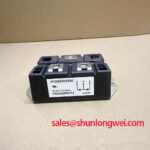
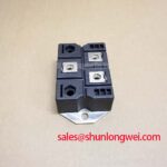


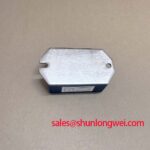
Content last revised on September 22, 2026
Preventing Spurious Faults: AC Line Surge Immunity and Lightning Transient Guidelines for PSMD200E-12
For a medium-frequency induction melting or metal hardening power supply, the module normally operates inside a larger AC input protection system. The product data identifies a VRRM of 1200 V; it does not, by itself, certify the complete assembly against an external surge environment. Designers should therefore assess the incoming line, transformer arrangement, available fault current, and switching conditions before selecting protective components.
An MOV network placed ahead of the rectifier may be evaluated as a Design Consideration for limiting line-to-line and line-to-earth transient energy. Its continuous operating voltage must be coordinated with the actual AC supply and worst-case tolerance, while its surge-energy capability should be checked against the installation’s documented transient environment. An RC snubber may also be considered where the measured waveform shows excessive ringing across the power terminals. The correct values depend on the system impedance, switching frequency, wiring length, and measured transient waveform rather than on the module part number alone.
IEC 61000-4-5 can be used as a system-level reference when defining surge-test conditions, but the presence of this rectifier module does not mean that the finished furnace power supply independently meets that standard. The completed equipment should be tested with its enclosure, protection network, transformer, wiring, and control electronics in their actual configuration.
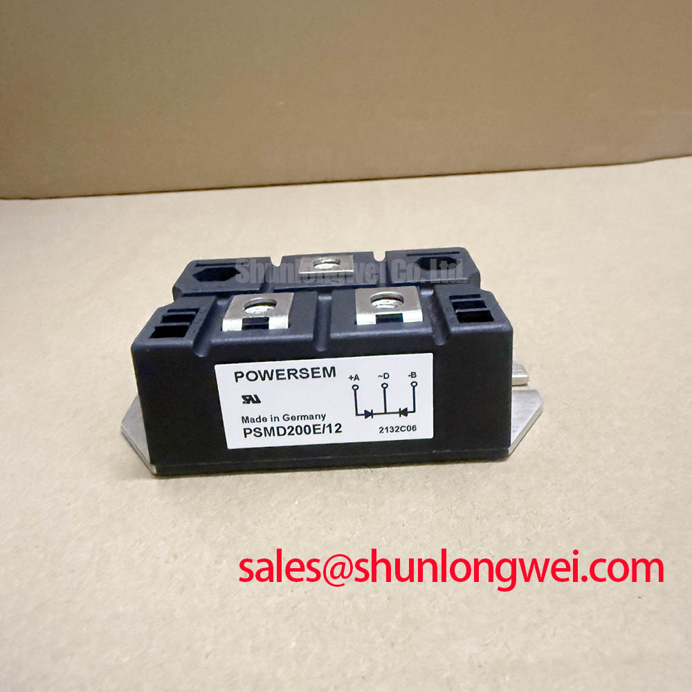
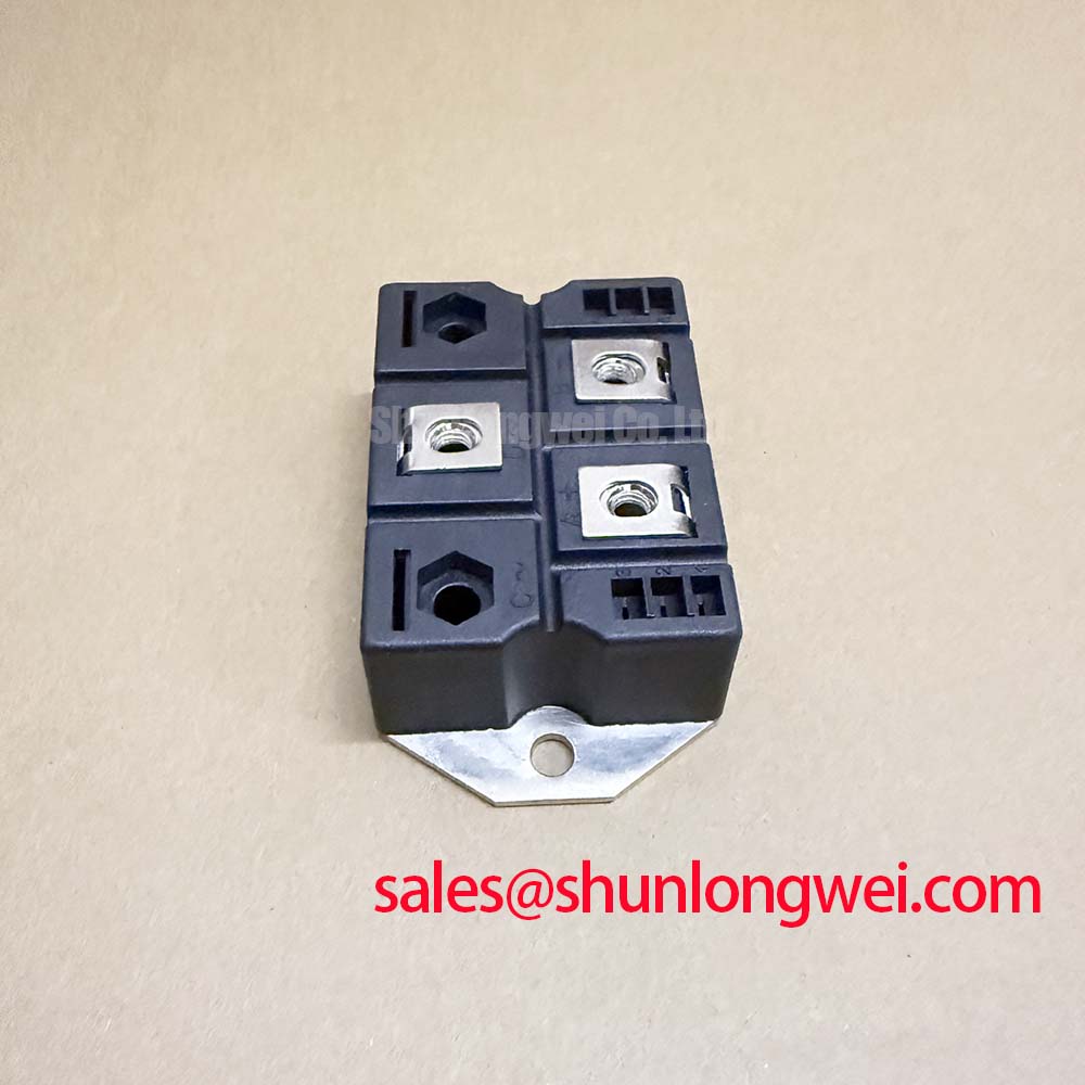
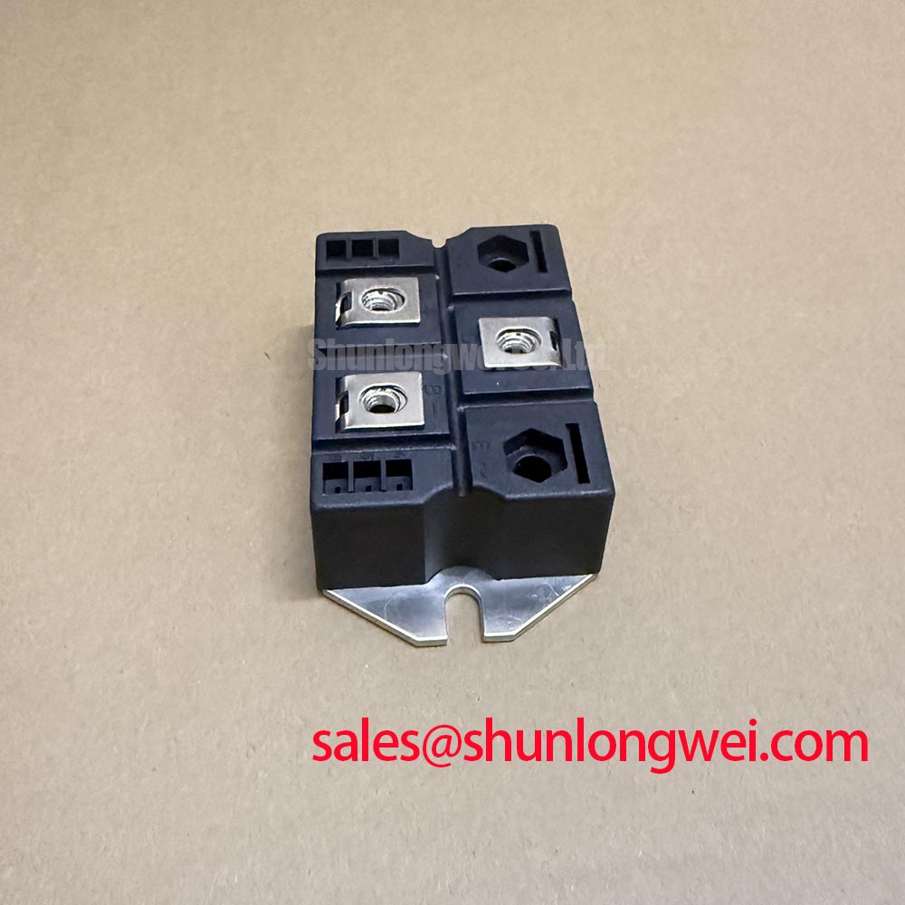
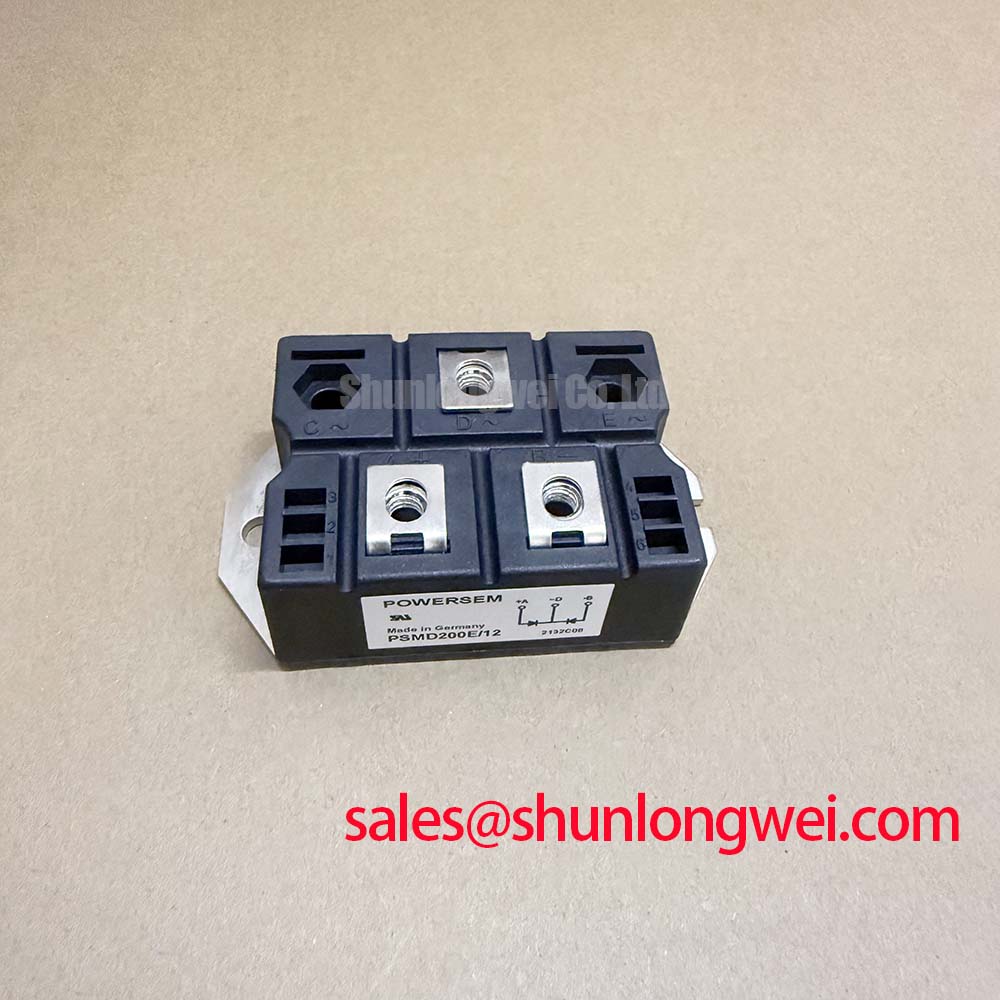
Before applying power, inspect the terminal arrangement from the original NIEC documentation and compare it with the equipment drawing. Do not infer terminal polarity from physical symmetry. Verify the AC input and DC output paths with the assembly schematic, then confirm that the fuse, contactor, MOV, and snubber connections are placed on the intended conductors. A fuse coordination table for the complete design is required before selecting a semiconductor fuse; no fuse I²t value is provided in the supplied product data for this model.
💡 Bench Tip: Use ESD protection and compare cold-state resistance or diode-test readings with a known-good reference before connecting the module to a charged DC link.
Preventing Spurious Faults: Minimizing Commutation Turn-Off Voltage Spikes
In a controlled rectifier, commutation can produce voltage ringing when current transfers between conducting paths. The PSMD200E-12 specification supplied here confirms voltage class, current capability, thermal resistance, and maximum junction temperature, but it does not provide reverse-recovery current, reverse-recovery time, or a soft-recovery classification. Those switching characteristics must be confirmed from the applicable manufacturer datasheet before they are used in a loss or EMI calculation.
During evaluation, place the voltage probe and current probe so that the measurement loop does not add an artificial inductive overshoot. The test should observe the module terminals, the commutation path, and the protective network under the actual DC-link and load conditions. If the waveform contains a sharp turn-off spike or extended ringing, the engineering response may include reducing stray inductance, reviewing snubber placement, and checking the interaction between the rectifier, transformer leakage inductance, and control timing. These are Design Considerations, not guaranteed operating requirements for this individual part.
The same principle applies to an induction furnace control board containing an isolated gate or firing interface. The control designer should examine common-mode transient coupling between the power section and the firing circuit, especially where optical isolators or digital isolators are used near high dV/dt nodes. The required CMTI capability, isolation rating, pulse width, and propagation delay belong to the selected control component and the complete firing circuit; they cannot be inferred from the PSMD200E-12 rating.
A bootstrap supply used by a high-side driver also requires separate verification. Its capacitor must retain sufficient voltage during the intended high-frequency charge and discharge sequence, and the bootstrap diode’s reverse-recovery behavior should be checked against the driver topology. This is a system-level Engineering Recommendation: confirm the driver supply waveform with an oscilloscope while observing startup, repetitive firing, load changes, and fault interruption. The rectifier module’s 1200 V rating does not define the bootstrap voltage or capacitor value.
For a neutral compatibility review involving another high-power device, engineers may examine the published information for PGH50N16. Any substitution decision still requires confirmation of electrical topology, terminal arrangement, thermal interface, gate or firing requirements, and mechanical fit in the original equipment.
PSMD200E-12 Circuit Protection and Reliability: Calibrating I²t Sub-Cycle Protection
A short-circuit protection review should begin with the actual prospective fault current at the module terminals and the interruption characteristics of the proposed semiconductor fuse. The PSMD200E-12 data supplied for this page does not include a device I²t withstand value, surge-current rating, fuse coordination table, or short-circuit test result. It would therefore be unsafe to claim a specific fuse size or guaranteed zero-damage clearing performance from the part number alone.
The practical method is to collect the manufacturer’s fuse clearing I²t curve, the module’s permitted surge and fault withstand data, the transformer impedance, and the DC-link capacitance. Compare the fuse’s total clearing energy with the semiconductor’s documented withstand limit over the expected fault duration. The comparison should include pre-arcing and clearing intervals, because a fuse’s published let-through value may not represent the complete stress seen by the rectifier.
Protection should also be checked at the control level. A furnace power supply may use firing inhibit, contactor opening, crowbar protection, or DC-link discharge hardware. Each function has a different response time, and the system engineer should verify that the protection sequence does not leave the module exposed to an uncontrolled current path. The firing circuit should be tested with the power stage disabled first, followed by controlled low-energy tests and waveform recording.
Thermal data provides an important boundary for continuous operation. The specified junction-to-case thermal resistance is 0.18 °C/W, while the specified maximum junction temperature is 150 °C. These are Official Specification values, not a complete heatsink design. The final temperature depends on semiconductor losses, case temperature, interface condition, heatsink geometry, airflow or liquid cooling, and mounting flatness. Designers should verify the case temperature at the actual duty cycle rather than converting the thermal-resistance value directly into a guaranteed operating temperature.
For thermal packaging background, the discussions of silver sintering and high-temperature die attach and PPS engineering plastics provide general industry context. They should not be interpreted as confirmation of a specific internal material construction for the PSMD200E-12.
Assembly Integrity and Layout Architecture for Phase-Controlled Rectification
When integrating the PSMD200E-12 into a phase-controlled rectifier, first match the module’s terminal arrangement to the original circuit drawing and verify the intended current direction with the equipment schematic. The supplied product information confirms the 200 A average forward-current rating at Tc = 85°C; it does not provide a complete pinout, firing-angle operating range, gate trigger requirement, or commutation specification. Those details must be obtained from the applicable manufacturer documentation.
Firing-angle control changes the relationship between AC input voltage, average DC output, displacement power factor, and reactive demand. At larger firing angles, the power stage may deliver less average DC voltage while drawing a more phase-displaced current waveform. The exact result depends on whether the load behaves as a resistive, inductive, motor-driven, or regulated furnace load. Engineers should record line current, DC output voltage, displacement, distortion, and device temperature across the intended operating envelope rather than relying on an idealized transfer assumption.
Layout should keep the high-current commutation loop compact and physically separated from firing and measurement wiring. Minimize parasitic loop inductance to reduce turn-off overshoot, then verify peak voltage against the rectifier’s documented limits during switching tests. The AC conductors, DC conductors, snubber wiring, and protective-earth connections should follow the equipment insulation and creepage requirements applicable to the complete assembly.
Mechanical installation is equally important. The heatsink surface should be clean and flat, the interface material should be applied consistently, and the mounting hardware should be tightened according to the manufacturer’s mechanical instructions. Avoid using terminal screws to correct a misaligned busbar, and confirm that cable strain is not transferred into the module body. After assembly, repeat the cold-state electrical checks, inspect the fasteners and terminals, and conduct an insulated power-off verification before energizing the medium-frequency induction melting or hardening furnace.
Long-duration validation should include thermal mapping, repeated start and stop cycles, firing-signal observation, surge-protection inspection, and post-test terminal checks. General technology context for display and industrial electronics is available in The Ultimate Guide to Industrial TFT LCD Technology; its principles should be treated as background material rather than as a product-specific reliability certification.

