Content last revised on October 23, 2026
AUO G084SN03 V1 Replacement and Integration Checks
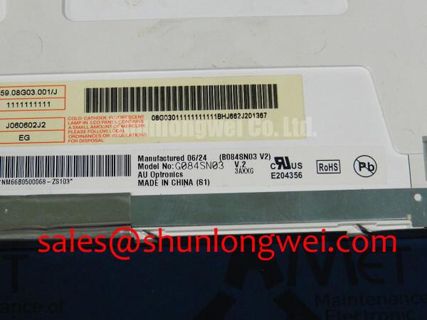
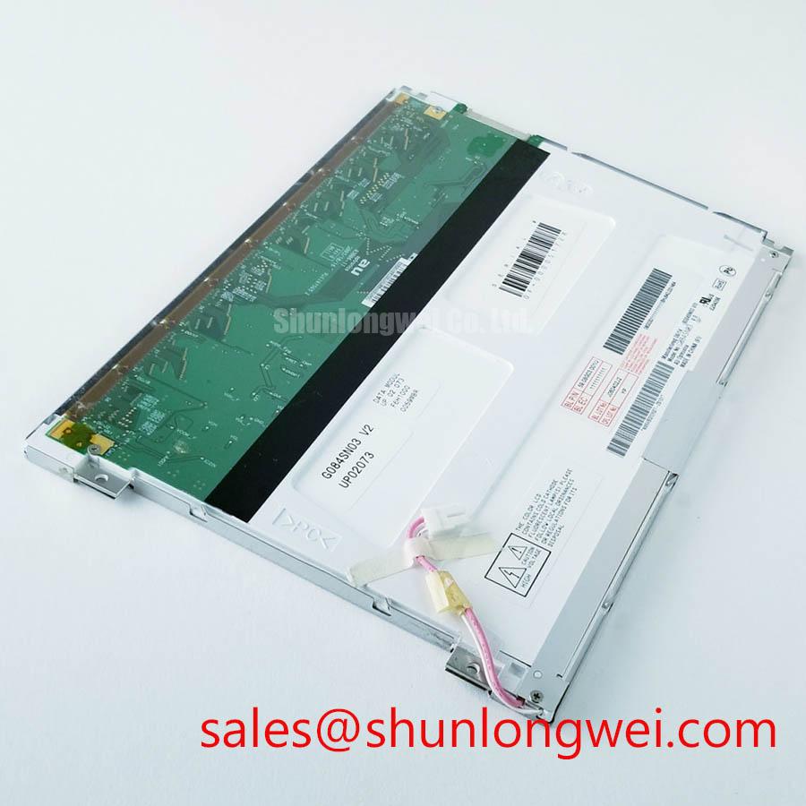
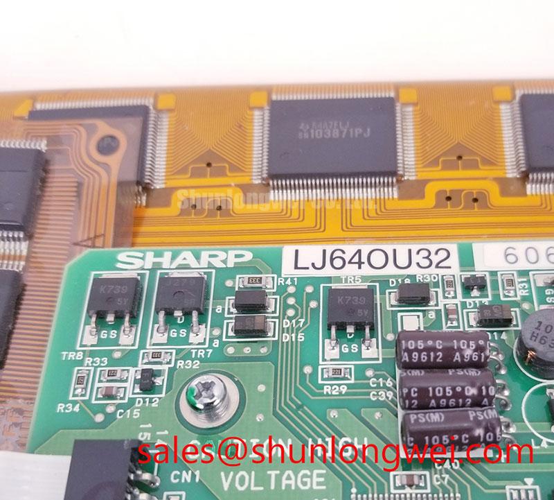
- Check the disconnected panel label for G084SN03 V1 and match the revision to the equipment service record.
- Inspect the LVDS cable contacts, connector orientation, and backlight wiring before reconnecting the display.
- Check bezel clearance and mounting support so the enclosure does not press against the viewing surface or distort the frame.
- Separate image-generation faults from illumination faults using a compatible controller and the correct CCFL inverter.
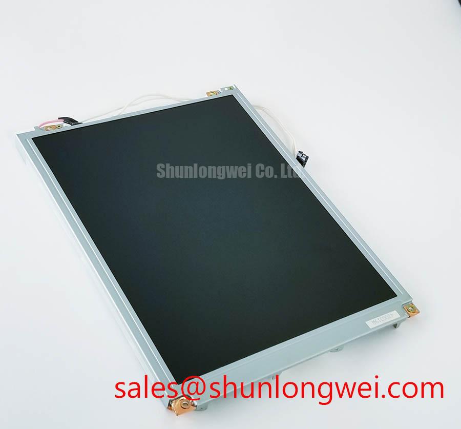
The AUO G084SN03 V1 is an 8.4-inch, 800 × 600 SVGA LCD display with a 20-pin, single-channel LVDS interface and CCFL backlighting. Replacement assessment should address the complete electrical, optical, and mechanical interface, rather than screen size alone.
| Parameter | Official Specification |
|---|---|
| Manufacturer and model | AUO G084SN03 V1 |
| Screen diagonal | 8.4 inches |
| Resolution | 800(RGB) × 600 pixels, SVGA |
| Luminance | 250 cd/m² typical |
| Contrast ratio | 600:1 typical |
| Viewing angles | 80°/80°/80°/60° typical, at CR ≥ 10; confirm directional order in the optical specifications |
| Signal interface | LVDS, single channel, 6/8-bit, 20 pins |
| Backlight | CCFL |
| Backlight life specification | 30,000 hours minimum; manufacturer test conditions and endpoint definition govern interpretation |
| Integration details | Supply voltage, pin assignment, timing limits, outline dimensions, and mounting tolerances: consult the revision-specific datasheet |
Suppressing Localized Thermal Gradients to Prevent Chronic Optical Yellowing (Color Shift)
Compare edge temperature and displayed white-field uniformity after the assembly reaches a stable operating condition. Design Consideration: a localized warm region can affect optical appearance, but yellowing alone does not identify a particular internal material or prove permanent thermal damage. Compare the same image at consistent brightness, viewing angle, and ambient illumination before attributing a color shift to the panel.
For enclosure integration, evaluate whether nearby power electronics or the inverter concentrate heat along a narrow display edge. A chassis-coupled spreader may help redistribute heat, provided its contact arrangement does not load the glass, obstruct wiring, or distort the frame. Rail dimensions and thermal interfaces belong to the enclosure design and should follow temperature measurements and mechanical clearance checks.
This model uses CCFL illumination, so LED-specific L70/B50 terminology should not replace its stated backlight-life specification. The minimum-hour figure is not a prediction of installed equipment service life. Cold-start behavior, illumination stability, and image response should be assessed separately within documented operating limits; a heater is not an assumed panel accessory.
Viewing-angle behavior also deserves attention when comparing replacement displays. Background references on IPS viewing-angle technology and LTPS TFT backplanes describe distinct display technologies; neither establishes that this AUO model uses those structures. Judge the installed panel against its specified angles and the actual operator sightline.
20-Pin/30-Pin Differential LVDS Timing, Pixel Clock & Skew Compensation
Map the 20-pin LVDS interface signal by signal before evaluating any controller adapter. A connector with a different pin count is not interchangeable merely because both assemblies carry LVDS. Compare supply and ground assignments, differential pairs, connector orientation, and controller output configuration against the revision-specific interface drawing.
Design Consideration: LVDS describes electrical signaling, not a universal pixel mapping. Align the controller’s channel arrangement, color depth, and JEIDA/VESA mapping where applicable. Incorrect mapping can alter colors or grayscale, while unstable timing or poor signal integrity can create intermittent image artifacts. Use controlled color patterns to distinguish these mechanisms rather than treating every split image as a cable fault.
Route differential pairs with controlled impedance and balanced geometry, minimizing discontinuities through connectors and adapters. The familiar 100 Ω differential impedance is a general LVDS design reference, not a measured property of an arbitrary replacement cable. Evaluate the complete channel against receiver requirements using an appropriate measurement setup.
Engineering Recommendation: preserve differential-pair symmetry through the cable and adapter, then validate clock-to-data timing at the receiver instead of relying on equal trace lengths alone.
Capture panel power, valid video, and inverter enable during startup and shutdown. Their sequence must follow the panel and inverter requirements. Because the backlight is CCFL, dimming compatibility depends on the inverter’s control interface; an LED constant-current driver is not an equivalent substitute. Assess brightness response and flicker across the supported dimming range without imposing a generic PWM frequency.
Incoming Benchtop Inspection: COG/TAB Anisotropic Conductive Film (ACF) Integrity
Display solid red, green, and blue fields, then white, black, and grayscale patterns using a compatible source. Record whether a defect follows image content, remains at a fixed screen location, or changes as the assembly warms. This separates observable behavior from assumptions about COG, TAB, or ACF construction that the external symptom cannot establish.
Design Consideration: a faint image visible under oblique illumination can help distinguish absent backlighting from absent image generation, but it does not identify the failed component. Inspect inverter enable and fault behavior alongside lamp connections. Open-load or short-circuit protection belongs to the inverter implementation; protection thresholds and diagnostic outputs must come from that inverter’s documentation.
Persistent lines require comparison with a known-good source and cable before attributing them to panel interconnect damage. Avoid pressing the bezel or flexing the assembly as a diagnostic shortcut. For grayscale distortion, check controller configuration and supply stability before investigating accessible gamma-reference circuitry under the relevant service procedure; adjustment is not a substitute for fault isolation.
The 600:1 typical contrast ratio does not establish sunlight readability. Ambient reflections, cover glass, and any added touch layer affect observed contrast. Anti-glare or anti-reflection treatment should be treated as an assembly characteristic, not an assumed G084SN03 V1 feature.
Eye-Diagram Voltage Margin & Differential Noise Floor Verification in High-Vibration Bays
Measure LVDS behavior with a differential probing arrangement that minimizes loading, then correlate image disturbance with equipment operating states. Design Consideration: compare differential amplitude, common-mode movement, and timing consistency at the receiver; a clean controller-side waveform does not establish margin after the cable and connectors.
When evaluating compatibility with a factory-automation machine-tool HMI operator terminal, inspect cable restraint, bend transitions, and separation from motor-power wiring. Shield termination should follow the equipment grounding architecture. Ferrites are an option for measured common-mode interference, not a default cure for pixel jitter or horizontal bands. Validate any change under the operating condition that produced the disturbance.
The Industrial Display & HMI Solutions engineering guide provides broader integration context for enclosure, cabling, and environmental assessment. Panel selection alone does not establish complete-equipment EMC compliance.
Close the mechanical assessment by checking bezel overlap, connector access, and cable movement with the enclosure assembled. If a separate touch overlay is fitted, evaluate glove and wet-surface response through its own controller settings, while checking that overlay pressure and reflections do not compromise display performance.