



Content last revised on September 10, 2026
Suppressing Pixel Jitter and Horizontal White Lines Induced by Adjacent 400V Motor Drives
When this panel is evaluated near a variable frequency motor drive, begin with cable routing rather than changing display settings. A 400V drive can produce strong electric and magnetic field transients during switching. Pixel jitter, intermittent horizontal bands, or unstable image regions may result from the complete display link, grounding arrangement, connector seating, or the host controller. These symptoms should not be assigned to the LM64C351 alone without comparison testing.
A practical inspection starts with the cable shield termination at both ends of the display path. The system integrator should verify whether the original equipment uses a full circumferential shield connection, a chassis reference, or a controlled single point connection. A long pigtail connection can increase susceptibility to common mode noise. The correct arrangement is system dependent and should be confirmed by observing the signal return path, chassis bonding, and drive cabinet layout.
Where the original equipment includes an LVDS or other differential display link, inspect the cable for crushed sections, sharp bends at the connector, incomplete locking, and separation from motor phase conductors. A common mode ferrite may be evaluated as a Design Consideration when conducted interference is observed, but its impedance profile, placement, and current rating must match the actual cable and signal environment. Adding an unverified filter can also affect edge quality, so the result should be checked at the receiver with a suitable oscilloscope probe arrangement.
For a replacement assessment, compare the suspect display with a known working signal path under the same image pattern. A fixed white field, black field, red, green, and blue fields can expose whether the disturbance follows the panel, the cable, the timing controller, or the drive operating state. Record the image condition with the motor drive disabled, enabled at low output, and operating through its normal speed range. This comparison is more useful than treating one visible line as proof of a particular internal failure.
Backlight ageing also requires careful wording. A statement such as 50,000 hours to 50 percent brightness is not an official LM64C351 specification in the supplied data and must not be used as a verified life rating for this model. If a constant current backlight driver is present in the equipment, the maintenance team should measure brightness at a consistent camera exposure and test temperature, then compare the result with the original equipment baseline. Any MTBF or lumen maintenance curve should come from the applicable Sharp documentation or a qualified system test report.
For a wider display-system review, the engineering notes in Industrial Display and HMI Solutions can be used alongside the equipment wiring drawings. This is a system design resource, not a substitute for the LM64C351 panel documentation.
Bench Tip: Disconnect power completely before removing the display cable, protect the panel and connector from ESD, and make sure the flexible cable is perfectly aligned before closing its lock.
Flashlight Dark Shadow Optical Diagnostic to Isolate Logic and Backlight Failure Modes
Perform the optical check in a controlled inspection area with the display driven by a known valid image. First apply full-screen red, green, blue, white, and black patterns. Look for stationary dark regions, repeated vertical features, horizontal lines, uneven illumination, and defects that remain fixed while the image changes. The objective is to establish whether the panel is receiving and forming image data before drawing conclusions about the backlight.
Next, use a flashlight at approximately a 45-degree angle to inspect a dark screen. A faint image visible in the shadowed area can indicate that image information is present while the illumination path is inadequate. This observation is a diagnostic clue, not a guaranteed fault signature. Check the backlight driver enable signal, current regulation, connector contacts, and host power sequence against the original equipment records.
If the image itself contains a persistent line or a group of missing pixels, repeat the test with different primary-color fields and with a slow change between black and white. A defect that follows image content may require investigation of the timing controller, data link, or panel drive path. A defect that remains in one physical location may involve the panel assembly or its connection. Without an authorized internal construction record, the inspection should not claim a specific COG fracture or bonding mechanism.
Physical pressure should not be used as a repair method. Pressing the glass edge, flex area, or connector can change the symptom temporarily while creating additional mechanical stress. Instead, inspect the connector for contamination, uneven insertion, latch damage, and cable creasing. Photograph the screen at identical exposure settings so that a procurement or repair team can compare the condition with the removed unit.
For high EMI installations, the differential pair layout is a Design Consideration. A nominal 100 ohm differential characteristic impedance with a tolerance such as plus or minus 10 percent, and controlled pair skew such as no more than 50 picoseconds, may be used by a system designer where the transmitter and receiver documentation calls for those conditions. These figures are not verified electrical specifications for the LM64C351 itself. The final routing must follow the original interface standard and be validated with the actual controller, cable, and connector.
When the application is a high precision surgical navigation or ultrasound diagnostic display terminal, a dark shadow test is especially useful before replacing the panel. It can prevent a backlight driver or cable problem from being incorrectly attributed to the LCD module. Any equipment used in a regulated medical environment also requires separate system-level validation; the panel description supplied here does not constitute a medical safety or EMC certification.
20 Pin and 30 Pin Differential LVDS Timing, Pixel Clock and Skew Compensation
Do not identify the LM64C351 connector by pin count alone. The supplied factory information confirms the display module category but does not provide a verified 20-pin or 30-pin pin assignment, LVDS mapping, logic supply voltage, pixel clock limit, enable sequence, or data polarity. The system integrator should verify the required supply voltage and interface format from the original panel documentation before connecting power.
During bench replacement, first trace the host board cable from its connector to the timing controller or display transmitter. Mark the supply, ground, clock, data pairs, enable control, and any backlight-related conductors only after confirming them from the equipment schematic. A connector that appears mechanically compatible can still have a different power position or data mapping.
Power sequencing should be measured at the panel connector with the display disconnected or connected according to the service procedure. Check the rise and fall behavior of the logic rail, display enable, reset, and video activity. The often-cited range of 0.5 milliseconds to 10 milliseconds for a supply rise interval is a Design Consideration for some display systems, not an official LM64C351 limit in the supplied data. Use the timing requirements of the original controller and panel documentation instead.
Incorrect JEIDA or VESA mapping can produce split screens, swapped color channels, unstable synchronization, or an image with incorrect grayscale progression. These symptoms can also arise from a cable fault or unsuitable transmitter configuration. Compare the replacement panel’s documented mapping with the controller firmware and, where available, verify clock and data activity at the receiving side. Do not change mapping by trial and error while the panel is energized.
For differential routing, maintain consistent pair geometry, avoid unnecessary stubs, and provide a controlled return path. The system engineer should compensate for trace length differences only after measuring the complete channel, including board launch, cable, connector, and receiver input. Oscilloscope measurements should use appropriate high-bandwidth differential probing because an unsuitable probe can create apparent ringing or skew that is not present in normal operation.
White-screen flashes during startup or residual images after shutdown should be assessed as power-sequencing symptoms rather than immediate proof of panel damage. Confirm that video data is held in the required state while the panel supply and enable controls transition. On power removal, check for delayed discharge paths and unintended back-feed through signal lines. The correct discharge and isolation method is determined by the host circuit and must be verified under repeated power cycling.
For an objective compatibility comparison, engineers may review the similarly categorized LM64P10, but a neutral comparison does not establish it as a direct substitute. Resolution, connector arrangement, optical characteristics, timing, mounting geometry, and software configuration must all be matched independently.
Surface Anti Glare and Anti Reflective Etched Coating for High Ambient Readability
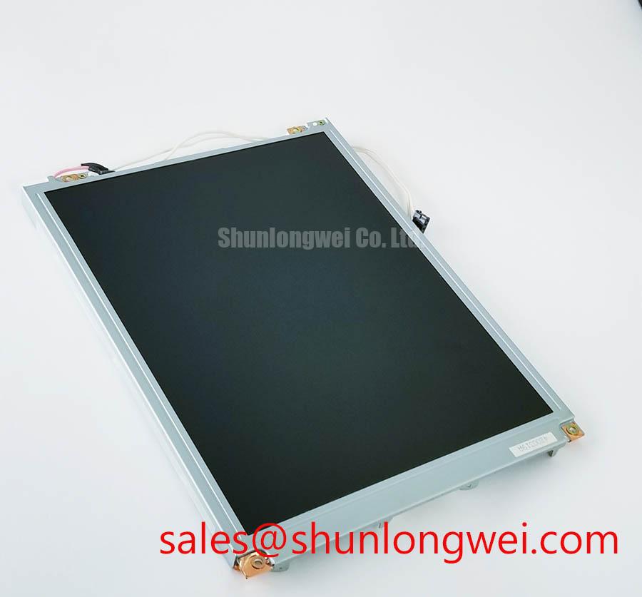
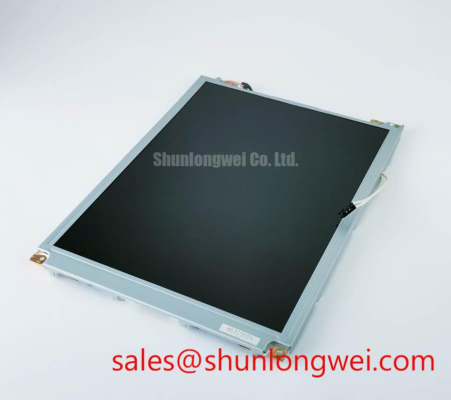
Inspect the front surface under diffuse room light before powering the module. Look for scratches, pressure marks, uneven reflections, contamination, and changes in surface texture across the active area. A surface that appears acceptable under a dark test pattern may reveal reflections or haze when viewed with a bright white field. Optical acceptance should be based on the original equipment requirement because the supplied LM64C351 data does not list a confirmed AG or AR coating specification.
Anti-glare treatment can reduce mirror-like reflections, but it may also alter perceived sharpness, grain structure, and black-level appearance under strong ambient illumination. Anti-reflective treatment works through a different optical approach and should not be assumed to be present simply because a panel is intended for industrial HMI use. The system integrator should verify the actual surface treatment from the applicable Sharp documentation or the original panel sample.
Viewing-angle evaluation should use controlled test images rather than a single photograph. Check grayscale steps, skin-tone or neutral images, and fine text from the operator’s normal position and from practical side positions. TN, IPS, and MVA descriptions refer to different panel technologies, but the supplied product information does not confirm the LM64C351’s specific optical mode. Do not assign an 85 degree viewing-angle value in four directions to this model without a factory source.
Wide-angle viewing can still produce changes in contrast, grayscale, or color balance depending on the panel structure, polarizer behavior, ambient light, and drive settings. A display used in an ultrasound diagnostic or surgical navigation terminal should therefore be evaluated with the actual enclosure window, protective cover, illumination, and viewing position. Optical bonding, if considered for a future assembly, should be treated as a system integration decision involving moisture control, optical reflection, serviceability, and thermal expansion. It is not confirmed as a construction feature of the LM64C351.
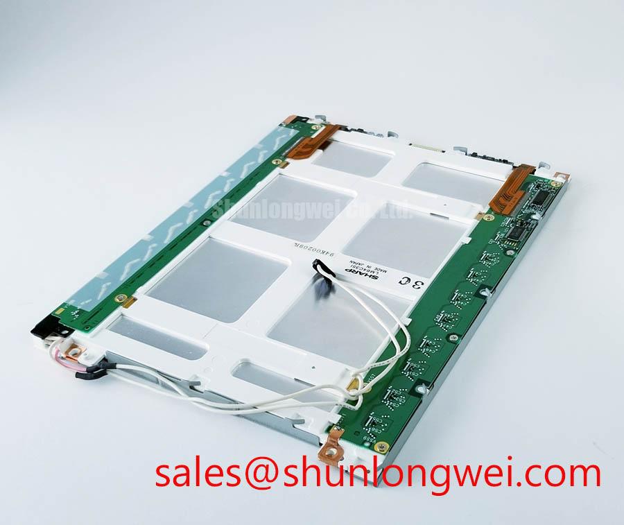
The backlight and surface should be tested together because uneven illumination can be mistaken for coating nonuniformity. Capture a white field at the intended operating brightness, then inspect the same area with the light source disabled when the equipment permits safe testing. If the module uses a separate backlight assembly, the integrator should verify its electrical interface and replacement procedure from the original equipment documentation rather than assuming a universal LED or CCFL arrangement.
For supporting display-chain evaluation, the separately listed LMS700KF01-001 may be reviewed as a related display solution. Its presence in a product portfolio does not confirm electrical or mechanical compatibility with the Sharp LM64C351. Final acceptance should combine the verified panel identity, connector documentation, image-pattern results, power-sequence measurements, and enclosure-level optical inspection.