

Content last revised on October 14, 2026
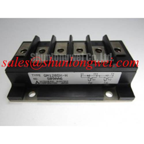
QM120DX-H Identification and Bench Inspection
With the power stage disconnected and its stored energy discharged, match the QM120DX-H terminal markings to the equipment schematic before placing a meter across any junction. Record probe polarity and isolate parallel circuit paths that could alter the reading. For this Mitsubishi Electric device, the supplied product specification identifies an Isolated Darlington Module with a listed current of 34.0 A; incoming inspection should therefore follow bipolar transistor terminal conventions rather than assume an IGBT gate interface.
The voltage entry is Standard Industrial Rating, not a numerical blocking-voltage specification. Consult the manufacturer datasheet for the voltage limits, current-rating conditions, terminal diagram, and approved insulation test procedure before accepting the module for powered evaluation. Keep those acceptance documents alongside the QM120DX-H product record so purchasing and bench personnel work from the same identification details.
💡 Bench Tip: Use ESD precautions and compare cold-state readings with a documented reference module using the same meter, probe polarity, and temperature conditions.
Transient Dynamics & Electrical Design: Preventing High di/dt Gate-Loop-Induced Transients on QM120DX-H
Trace the base-drive return to the emitter connection identified in the terminal diagram, rather than treating every emitter-connected conductor as an interchangeable return. The gate-loop terminology in this diagnostic topic must be translated to a Darlington base-drive circuit: base current controls conduction, and stored charge influences turn-off. A dedicated auxiliary or Kelvin emitter terminal must not be assumed from the module name or isolated package description.
As a Design Consideration, shared impedance between the load-current path and the driver return can disturb the voltage seen by the drive circuit during current transitions. Inspect where the driver reference joins the power circuit, how the outgoing and returning drive conductors are routed, and whether their loop passes close to switching conductors. The objective is to reduce unintended coupling without changing the terminal assignments established by the equipment schematic.
For cold-state screening, use the meter’s diode function only on terminal combinations supported by the circuit diagram. Record forward and reverse readings rather than applying a generic pass threshold. A Darlington module’s measured response can depend on its documented internal circuit and the instrument’s test current. An unexpected reading warrants checking contact quality, residual charge, connected components, and the measurement direction before attributing it to a defective semiconductor.
During controlled powered evaluation, observe the base-to-emitter drive at the module connection and correlate it with collector-current transitions. As an Engineering Recommendation, use probes rated for the circuit potential and avoid measurement connections that introduce an unsafe earth reference. Compare the commanded turn-off event with the actual current decay; an observed disturbance can originate in the driver, shared return impedance, or the measurement arrangement itself.
Physical routing also needs an insulation-aware review. Keep drive wiring away from exposed power connections and preserve the equipment’s specified separation around terminals. Clearance depends on the working voltage, insulation system, contamination conditions, and applicable equipment standard; it is not a universal spacing that can be inferred from this part number. Photograph the original routing before dismantling so that a repair does not inadvertently introduce a larger coupling loop.
For compatibility assessment, the CM400DY-12 provides a separate power-module comparison reference, not a same-specification replacement recommendation. Compare semiconductor technology, drive requirements, terminal mapping, mounting geometry, and switching behavior before considering any change. Engineers evaluating light industrial automation or multi-joint robotic actuator drives should retain the original controller and power-stage requirements as the acceptance basis.
QM120DX-H Operational Boundaries: Evaluating Isolated DC-DC Power Supply Sizing for High-Voltage Limits
Assess an isolated driver supply against the complete base-drive load, including sustained drive demand, turn-off behavior, and the driver’s own consumption. As a Design Consideration, a Darlington drive circuit cannot be sized from an IGBT gate-charge calculation alone. The supply must support the documented drive waveform without excessive droop or an unintended change in transistor conduction.
Examine supply behavior at the driver terminals rather than relying only on its nominal output rating. Capture startup, commanded switching, and shutdown while observing the relationship between supply voltage and drive output. Local energy storage and supply impedance affect that relationship, but component values should follow the driver requirements and measured operating conditions. Check that a supply interruption produces the intended disabled state instead of leaving the base-drive circuit uncontrolled.
Isolation withstand voltage, reinforced-insulation classification, and common-mode transient immunity are separate properties. Evaluate each against the driver and isolated supply manufacturers’ documentation and the equipment’s safety requirements. Neither the word “isolated” in the module package description nor a driver’s transient-immunity rating establishes reinforced isolation for the complete assembly. Acceptance should identify which barrier is being assessed and what operating stress it must withstand.
As an Engineering Recommendation, minimize the commutation loop area to reduce inductive voltage overshoot during turn-off, then verify the resulting collector-emitter waveform under the intended operating conditions. Follow the outgoing and returning power paths together through the module, DC-link connection, and any existing suppression components. Long connections can undermine a suppression network even when its individual components remain serviceable.
Where the equipment uses a film-capacitor snubber, inspect its connection geometry, terminal condition, and specified pulse capability. Where a metal-oxide varistor is present, assess its coordination with the bus voltage and repetitive transient exposure using the original circuit requirements. A snubber and a varistor have different operating roles; neither should be added or resized solely because a switching spike appears on an oscilloscope capture.
Thermal evaluation should accompany any drive or switching change. As a Design Consideration, pulse heating depends on the loss waveform and the applicable transient thermal impedance, not merely the listed current. Use the module’s documented thermal data with the equipment duty cycle and measured case conditions. A shorter switching event does not by itself establish an acceptable junction-temperature excursion.
The broader discussion in The 1200 V CoolSiC™ MOSFET Advantage in Three-Phase Power Conversion offers context for switching-loss and layout tradeoffs in another semiconductor technology. Its MOSFET-specific drive assumptions and numerical limits should not be transferred to the QM120DX-H Darlington circuit.
QM120DX-H Circuit Protection & Reliability: Calibrating Megohmmeter DC High-Potential Terminal-to-Baseplate Tests
Separate an insulation-resistance measurement from a dielectric-withstand test before connecting a megohmmeter between the electrical terminals and baseplate. They answer different questions and can impose different stresses. Apply only the manufacturer-approved terminal grouping, test voltage, duration, and discharge procedure; an arbitrary high-potential test can damage a module or connected electronics rather than establish serviceability.
As an Engineering Recommendation, disconnect sensitive circuitry and inspect the exposed insulating surfaces before testing. Remove contamination using an approved cleaning method and allow the assembly to dry. Record surface condition, temperature, humidity, instrument identity, and connection arrangement so that an abnormal result can be investigated reproducibly. A low reading may reflect external contamination, a connected leakage path, or an internal problem; the reading alone does not identify which explanation applies.
The isolated package designation does not establish a particular ceramic substrate construction. Inspection should concentrate on accessible evidence: cracks around terminal supports, damaged insulating surfaces, contamination tracks, and the condition of the baseplate interface. Manufacturer documentation accessible through Mitsubishi Electric semiconductor resources is the appropriate authority for device-specific test limits and construction details.
Measurement traceability matters when insulation results determine acceptance. The National Institute of Standards and Technology provides authoritative metrology resources, but does not constitute product-specific approval for this module. Maintain instrument calibration records and distinguish a resistance result from evidence of compliance with an equipment safety standard.
For reassembly, check heatsink contact condition and use the specified thermal-interface material and fastening procedure. As a Design Consideration, uneven contact or uncontrolled material application can impair heat transfer. Do not import press-pack spring loading, double-sided clamping, or generic bolt torque into this isolated module’s mounting procedure.
Finally, review the existing fuse and shutdown coordination before returning the power stage to operation. Fuse clearing behavior must be assessed against the semiconductor’s documented fault capability and the circuit’s available fault energy; a fuse rating alone does not establish module protection. Retain the inspection results, insulation-test record, mounting checks, and observed shutdown response with the equipment repair record.