
Content last revised on October 21, 2026
QM600HA-24 Operational Boundaries: Evaluating Cold-State Main Terminal Impedance Limits
- Measure cold, unpowered impedance across the main terminals and the antiparallel diode path with the digital multimeter in diode check mode.
- Confirm the installed heatsink, pressure plate, thermal interface, and dual sided cooling arrangement are clean, flat, and correctly aligned.
- Inspect base drive isolation, auxiliary emitter return routing, and driver board insulation before applying DC link voltage.
- Record terminal temperature rise, base waveform symmetry, and protection response during controlled commissioning.
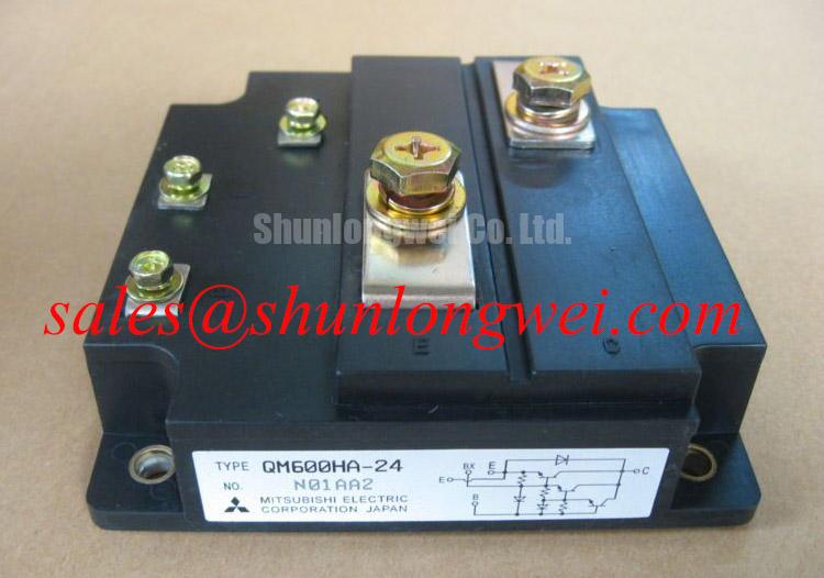
The Mitsubishi Electric QM600HA-24 is an isolated Darlington module rated at 1200.0 V and 600.0 A according to the supplied official product specification. Its high current rating makes mechanical clamping, thermal transfer, base loop control, and protection coordination important parts of any replacement assessment. Engineers evaluating a unit for a multi megawatt offshore or onshore wind turbine full scale converter should compare the electrical topology, driver interface, cooling arrangement, and protection sequence with the existing equipment before installation.
| Manufacturer | Mitsubishi Electric |
| Model | QM600HA-24 |
| Rated voltage | 1200.0 V, Official Specification |
| Rated current | 600.0 A, Official Specification |
| Package | Isolated Darlington Module, Official Specification |
| Product category | Power Transistor / Darlington Module |
Cold-state screening should be completed with the module fully isolated from the DC link, base driver supply, control wiring, and discharge circuits. Use the meter’s diode-check function to compare the forward response between the relevant main terminals and the antiparallel diode path. The purpose is comparative screening against a known-good assembly, not the assignment of an unsupported pass or fail voltage. A highly asymmetric reading, an unexpectedly conductive path in both polarities, or a completely open path where a semiconductor junction is expected should trigger further isolation of the module from surrounding snubbers, bus capacitors, and clamp networks.
Base leakage should be checked separately with the base terminals disconnected from the driver board. Keep the test instrument at a controlled low-energy condition and avoid charging the base through an uncontrolled external source. A leakage reading that changes as the harness is moved may point toward contamination, connector damage, or insulation stress in the external circuit rather than proving an internal module defect. Record the test polarity, ambient temperature, meter range, and terminal configuration so that the maintenance record remains useful during a later comparison.
The physical installation has equal importance. The heatsink contact surface should be clean and free from burrs, while the pressure plate should apply even force across the module’s cooling interface. When a dual sided cooling arrangement is used, both thermal paths need the same inspection standard. Thermal interface material should be spread uniformly according to the module and heatsink assembly instructions; excessive compound, uneven pressure, or a tilted clamping plate can increase thermal resistance and create local temperature differences.
Clearance around the high voltage terminals should prevent accidental contact with the heatsink, mounting hardware, cable shields, or nearby laminated buswork. The system designer should also verify creepage, clearance, insulation barriers, and enclosure contamination control for the actual converter environment. In wind turbine converters, salt moisture, condensation, vibration, and restricted cabinet airflow can change the electrical and thermal conditions without changing the module’s nameplate ratings.
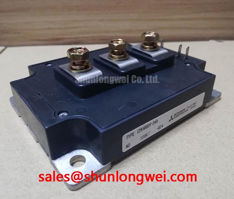
For a replacement assessment, the CM400HU-24H may be reviewed as a separate compatible device option only after voltage, current, package geometry, base characteristics, thermal interface, and driver requirements have been compared by the system engineer. A similar product category does not by itself establish interchangeability.
Preventing Spurious Faults: Auxiliary Emitter Return Trace Separation Guidelines for QM600HA-24
The auxiliary emitter return should be routed as a controlled driver reference rather than sharing the high current emitter path. High di/dt current through the power return produces a transient voltage across stray inductance. If that voltage is allowed to appear in the base reference, the driver may see false feedback, unwanted base movement, or apparent oscillation. Keep the auxiliary return physically separated from the main power return until the intended reference point defined by the converter layout.
This separation is especially important when the module is connected to a compact base driver board through a cable or flexible harness. The base command path and its return should travel together, with the shortest practical loop and minimal exposure to collector bus transitions. The system integrator should verify the driver’s isolation rating, common mode transient immunity, and connector pin assignment against the actual control board. An optocoupler or digital isolator may be suitable depending on the circuit architecture, but its switching behavior and CMTI performance remain system-level design factors rather than properties assigned to the power module.
Desaturation protection should be coordinated with the driver and converter control logic. A design team may evaluate a short-circuit detection response within approximately 3 µs as an engineering starting target for fast protection, provided the driver propagation delay, blanking interval, sensing diode behavior, and noise immunity are characterized together. This is a protection design consideration, not an official QM600HA-24 switching specification. The detection circuit should distinguish a genuine high current event from voltage disturbance caused by parasitic inductance or a poorly referenced auxiliary return.
Two-stage soft turn-off is commonly considered when a sudden base-drive reduction would create excessive collector voltage overshoot. The first stage reduces base drive in a controlled manner, while the second stage completes turn-off after the high energy transition has been moderated. The timing, base resistance, clamp behavior, and fault latch response should be tuned from measured waveforms. Designers should verify the resulting peak voltage against the converter’s DC link and insulation coordination during controlled tests.
Maintenance Note: Recheck terminal tightness, heatsink cleanliness, and contact temperature rise during scheduled service, especially after periods of high cabinet humidity or restricted airflow.
Preventing Spurious Faults: Mitigating Hard Switching Transients: Guidelines for QM600HA-24
Hard switching transients are controlled by the complete commutation loop, not by the module rating alone. Keep the DC link capacitor, switching module, freewheel path, snubber, and return bus electrically compact while maintaining the required insulation distances. The goal is to reduce parasitic inductive voltage during rapid current change, then verify the remaining peak with a properly referenced differential probe.
For short circuit protection, the control architecture may distinguish Type I and Type II events according to the converter’s fault energy and operating state. A response interval below approximately 10 µs can be evaluated as a system design target for rapid short circuit detection, but it must include sensing delay, driver delay, base discharge behavior, and measurement uncertainty. This timing is not an official rating of the QM600HA-24. The protection sequence should be validated with a safe test method that does not expose the production converter to uncontrolled fault energy.
The two-stage soft turn-off approach described above can also limit the voltage step created by an abrupt interruption of current. A clamp network, snubber, or MOV arrangement may be coordinated with the switching loop to absorb part of the transient energy. MOV selection should consider repetitive pulse energy, clamping behavior, thermal recovery, and the actual line or DC bus fault environment. The module should not be treated as an independent surge protection device.
Converter topology affects the observed waveform. A buck converter uses controlled step down energy transfer, while resonant switching methods seek reduced switching stress through voltage or current transition shaping. Engineers can consult the Buck Converter Step Down Voltage Regulation reference and the discussion of Zero Voltage Switching Resonant Converters when comparing the installed topology with the replacement application. These references describe general power conversion principles and do not replace the converter manufacturer’s switching data.
Long motor or generator cables can behave as transmission lines at fast edge rates. Reflections may produce a second voltage peak at the switching terminals, particularly where cable impedance, termination, and motor input characteristics differ. Filtering and damping should be selected from measured cable behavior and the converter’s control requirements. The system engineer should verify both the module terminal waveform and the remote load waveform rather than relying on a single cabinet-side measurement.
Benchtop Waveform Tuning: Mitigating Stress via Thermal Feedback on QM600HA-24
Thermal feedback begins with a repeatable mechanical assembly. Clean both mating surfaces, apply the specified interface material consistently, and tighten the pressure system in the sequence defined for the heatsink and module assembly. A pressure plate that contacts unevenly can produce a misleading waveform and temperature result because one side of the power path may operate hotter than the other. Confirm fan direction, filter condition, duct sealing, and heatsink fin cleanliness before changing the base drive.
The positive temperature coefficient associated with static VCE(sat) can support current sharing under steady state conditions when parallel devices and their thermal paths are correctly matched. This behavior should be treated as an engineering consideration, not as permission to assume automatic dynamic sharing. During bench evaluation, compare collector emitter voltage, current waveform, case temperature, and base voltage for each parallel path under the same operating condition.
Dynamic balance depends heavily on symmetrical base loop wiring. Keep base and auxiliary return paths similar in length and geometry, avoid routing them beside high dv/dt collector conductors, and place the driver reference at the intended emitter point. If one waveform shows a different delay, ringing pattern, or turn-off slope, inspect the connector, return path, driver channel, and local base network before changing the power circuit.
Thermal measurements should be taken after the assembly reaches a stable operating condition and should be compared at equivalent load, switching frequency, airflow, and ambient temperature. A rising contact temperature may result from interface degradation, pressure loss, blocked airflow, current imbalance, or altered switching behavior. Trace the complete thermal path before assigning the issue to the QM600HA-24 itself.
When this module is evaluated in a full scale wind turbine converter, the maintenance plan should include heatsink cleaning, condensation inspection, terminal condition checks, insulation review, and trend monitoring of contact temperature. The replacement decision should also account for the driver board, protection timing, busbar geometry, cooling hardware, and cabinet environment rather than relying on voltage and current ratings alone.