
Content last revised on October 5, 2026
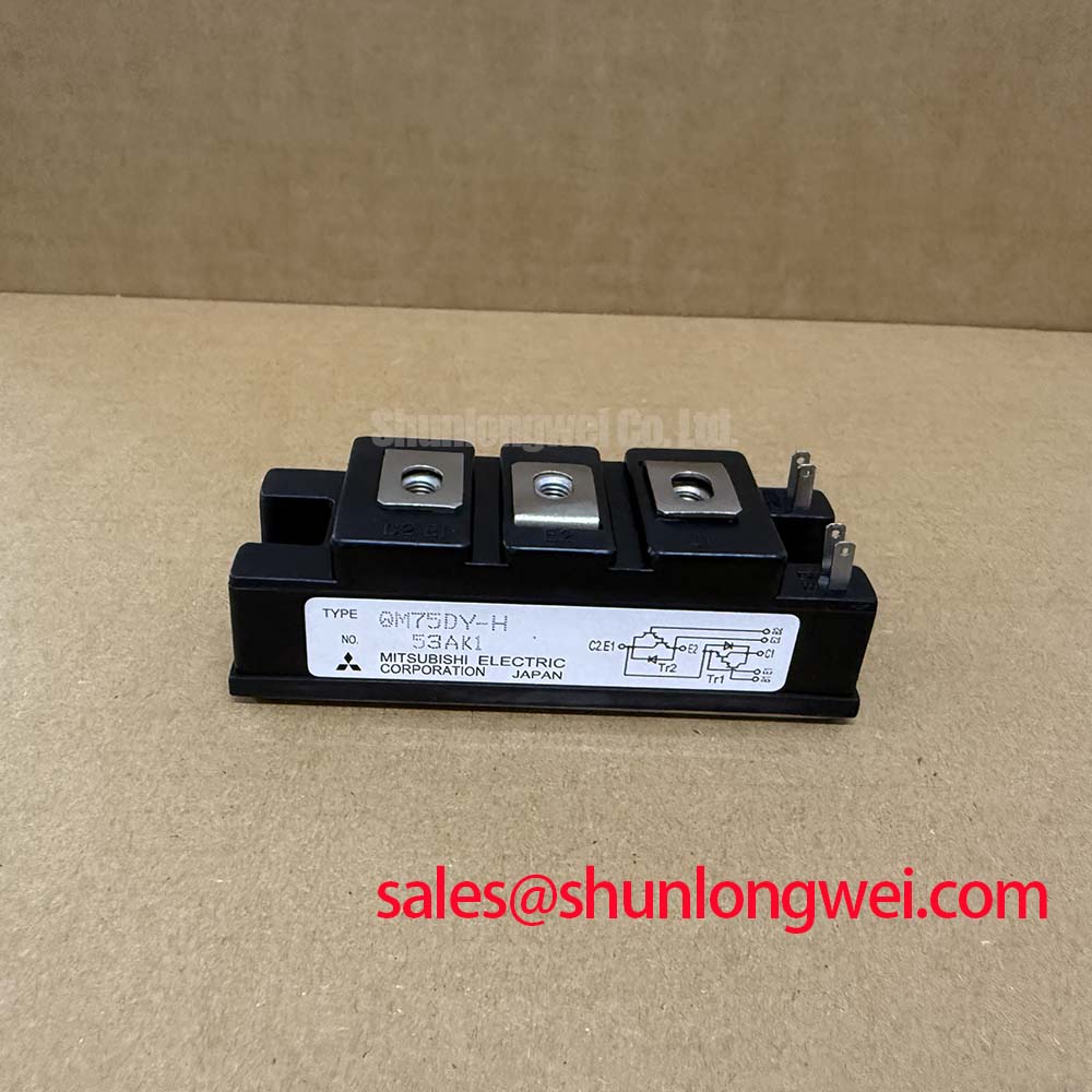
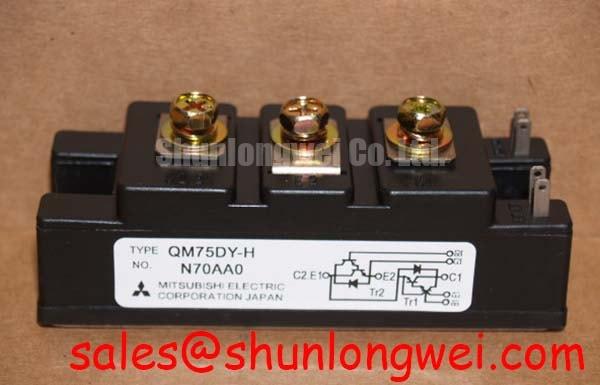
Field Diagnostics and Commissioning: Heatsink Contact in QM75DY-HB Assemblies
| Model | Manufacturer | Product category | Package | Rated voltage | Rated current |
|---|---|---|---|---|---|
| QM75DY-HB | Mitsubishi Electric | Power transistor module | Isolated Darlington Module | 600 V | 75 A |
The voltage, current and package entries listed above are Official Specifications. They identify a Darlington module, not an IGBT module; the installed circuit determines which switching and protection methods are applicable.
Measure the heatsink temperature beside the module during a controlled load run, then compare it with earlier readings taken at the same operating conditions. A rising trend calls for inspection of airflow, mounting pressure and the thermal interface before attributing the change to QM75DY-HB itself. With the equipment isolated and its stored energy discharged, inspect the seating surface for contamination, damaged fasteners and areas where the module does not sit evenly.
As a Design Consideration, apply thermal interface material as a continuous thin film rather than using excess compound to fill a mounting gap. Its thickness and the tightening sequence must follow the applicable module and heatsink instructions; neither a film thickness nor a screw torque is established by the specifications stated here. Bring mounting screws into contact progressively and check that tightening does not distort the assembly. Confirm electrical clearances against the actual busbar layout after reassembly, since an isolated package does not establish safe spacing for the surrounding circuit.
Maintenance note: Clean the heatsink air path and investigate any repeatable rise in module contact temperature before returning the equipment to sustained load. For a higher current reference during compatibility assessment, QM200HA-HK is a separate model to evaluate against the original schematic, mounting arrangement and drive requirements, not an assumed replacement.
Preventing Spurious Faults During Battery Cycling
Capture DC link voltage, module current and the fault signal across a battery charge to discharge transition if a microgrid converter trips during peak shaving. Compare the traces with a stable operating cycle before changing protection settings. Four quadrant power flow is a capability of a suitable converter topology and its controls, not a property established by the QM75DY-HB rating.
Repeated current swings can change semiconductor and heatsink temperatures faster than a steady load test reveals. As a Design Consideration, check whether the measured pulse profile, cooling response and protection thresholds remain compatible with the original equipment design. The 75 A Official Specification is a rated current, not permission to assume an unspecified pulse current or junction temperature margin. When examining the DC link, distinguish a genuine current excursion from a measurement disturbance by checking sensor wiring and the fault waveform together.
Review the actual drive schematic before applying a desaturation strategy: detection methods and turn off behavior used with IGBTs cannot be assigned to this Darlington module without circuit specific evidence. Where the power stage includes a separate rectifier or complementary switching position, QM100HY-2H can be examined as a distinct device in that topology; its role and compatibility require independent verification.
QM75DY-HB Circuit Protection: Investigating Switching Induced Faults
Probe the control terminal waveform and collector voltage together when a fault appears at a switching edge, using measurement equipment appropriate to the circuit potential. A disturbance coincident with a rapid voltage transition may indicate coupling through the power stage or its wiring, but it does not by itself prove cross conduction. Check the driver return path, control wiring separation and commanded switching sequence against a known good channel.
As a Design Consideration, keep the control loop compact to limit unwanted coupling, then verify switching waveforms at the installed DC link voltage. Set interlocks and dead time from the measured circuit behavior and the original control design, rather than importing a generic IGBT gate bias or active Miller clamp setting. If the circuit has a bootstrap supply, observe its voltage through the longest commanded on interval and during recharge; diode recovery and capacitor sizing depend on that driver and switching sequence, not on the module’s headline ratings.
Record peak collector voltage during turn off and compare it with the 600 V Official Specification under the conditions specified for the equipment. Cable reflections and recovery behavior in other power stage components warrant measurement where those elements exist, but neither a reflection multiplier nor a diode softness factor can be assigned to this module from the supplied specifications. Mitsubishi Electric’s power semiconductor resources provide broader device context; its CSTBT technology information concerns IGBT technology and should not be treated as a QM75DY-HB specification.
Field Diagnostics and Commissioning: Transient Heating Versus Heatsink Response
Log current pulses alongside heatsink temperature when the assembly passes a steady load check but faults under intermittent demand. The heatsink sensor may respond slowly while the semiconductor temperature changes rapidly, so a cool external reading alone cannot establish junction margin. Repeat the measurement after checking fan operation, blocked fins and the condition of the thermal interface.
A multi RC transient thermal model can help estimate junction temperature during pulsed loading, but an Engineering Calculation needs the correct device thermal impedance data, loss information and measured pulse history. Without those inputs, a numerical peak junction temperature would be unsupported. Review whether the protection event follows pulse duration, cooling conditions or a switching transition before changing the converter’s operating limits. For wider discussion of device selection and system level reliability testing, see the Power Electronics Masterclass; apply its principles only after identifying the technology and ratings of each installed device.