
Content last revised on September 21, 2026
Benchtop Waveform Tuning: Mitigating Stress via Fuse Total Clearing I2t versus Device Melt on RM500DZ-M
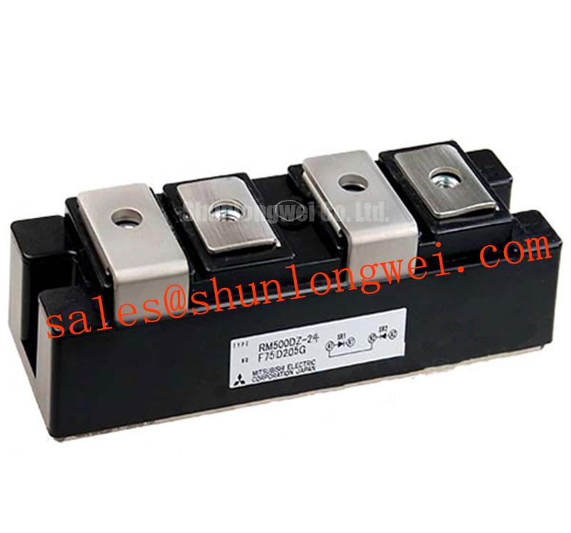
Before fitting the replacement part, verify the cabinet schematic and terminal labels against the rectifier leg, then confirm that the installed device is specified as a RM500DZ-M diode module with a 1600 V voltage rating and 500 A current rating. These are Official Datasheet Specifications provided for the Mitsubishi Electric module. The device is a power diode module, so its integration checks concern forward and reverse current paths, clamping stress, thermal interfaces, busbar geometry, fuse coordination, and cooling performance rather than gate drive or firing commands.
The module should be evaluated as one element in a complete power path. In a high current green hydrogen electrolyzer DC power rectifier, engineers should trace the incoming AC path, bridge arrangement, DC bus, smoothing reactor, protection fuse, and outgoing electrolyzer connection before deciding whether the module location, polarity, and electrical duty match the original equipment design. A diode module cannot control conduction angle; it conducts according to the applied circuit polarity and remains dependent on the surrounding transformer, rectifier topology, and load conditions.
| Parameter | Specification | Classification |
|---|---|---|
| Model | RM500DZ-M | Official identification |
| Manufacturer | Mitsubishi Electric | Official identification |
| Rated voltage | 1600 V | Official Datasheet Specification |
| Rated current | 500 A | Official Datasheet Specification |
| Package category | Diode Module | Official Datasheet Specification |
Start a dead short protection review by collecting the actual semiconductor fuse documentation used in the equipment, including its pre arcing and total clearing I2t information, voltage class, interrupting capability, mounting hardware, and coordination notes. The supplied RM500DZ-M product data establishes the module’s 1600 V and 500 A ratings, but it does not provide a module specific surge current curve, I2t withstand figure, terminal torque, or thermal impedance values. Those missing limits must be taken from the applicable manufacturer documentation for the exact module and from the original system records before any fuse coordination decision is made.
A fuse’s total clearing I2t represents the electrical stress let through until interruption, including the interval after its element begins to melt. The practical coordination question is whether the prospective fault current, the available source energy, and the fuse clearing behavior remain within the permitted fault capability of every semiconductor and conductor in the affected path. This review must include transformer impedance, DC bus capacitance, parallel bridge branches, cable inductance, and any stored energy on the electrolyzer side. A fuse selected only from its continuous current marking may not provide the required protection under a fast, high energy DC side fault.
On the bench, inspect the mechanical stack before applying electrical stress. Confirm that contact faces are clean, flat, and aligned with the mating busbars. Use the original equipment manufacturer’s specified terminal hardware and tightening procedure. Where the mounting instruction is unavailable, torque must not be inferred from a generic package category; the system integrator should obtain the applicable Mitsubishi Electric documentation or the equipment service manual.
🔧 Bench Diagnostic: De energize, isolate stored energy, and verify absence of voltage at the DC bus before loosening any module or fuse connection.
After a controlled repair, capture current and voltage at an appropriate protected measurement point during normal loading and during approved protection tests. A slower than expected interruption can indicate an issue in fuse selection, installed fuse condition, fault current assumptions, or the surrounding conductor path. It does not by itself identify a module defect. The resulting waveform record should be compared with the original equipment protection requirements rather than with a generic fuse rule.
Preventing Spurious Faults: AC to DC Transfer Characteristics across V Guidelines for RM500DZ-M
The AC to DC transfer characteristic of a diode bridge is fundamentally different from that of a controlled thyristor bridge. A diode module such as the RM500DZ-M has no gate terminal and no firing angle. Therefore, an alpha sweep from 0 degrees to 150 degrees is not a valid control characteristic for this product itself. If the rectifier cabinet contains controlled devices elsewhere, firing angle behavior belongs to those devices and their control system, not to the diode module.
For an uncontrolled diode rectifier, the DC output follows the available transformer secondary voltage, phase arrangement, source impedance, commutation overlap, and load current. In a high current electrolyzer supply, changes in load demand can alter voltage drop, current sharing, transformer regulation, and ripple. Engineers should measure phase to phase voltage under the approved operating state, DC output current, DC ripple, and individual bridge path temperatures. These observations give a more useful basis for assessing the RM500DZ-M operating environment than applying a thyristor firing angle model to a diode path.
Reactive power and displacement power factor should likewise be assessed at the transformer and complete converter level. A diode bridge can impose non sinusoidal current demand on the AC supply, while a controlled bridge can add firing related displacement effects. The distinction matters when reviewing utility demand, transformer heating, harmonic mitigation, and supervisory fault thresholds. Engineers evaluating DC conversion stages connected to renewable sources may also find the operating context of maximum power point tracking useful, although an MPPT controller does not alter the basic diode behavior of this module.
In cabinets using isolated command, status, or protection circuits, common mode transient behavior should be verified across the installed signal isolation path. Isolation component selection and layout are system level matters. As a Design Consideration, keep high current commutation loops physically disciplined and separate sensitive measurement returns from power return paths where the original architecture permits. This helps reduce measurement disturbances that can be mistaken for control or sensing faults.
For rectifier repair planning, a technically adjacent module should be compared by verified drawing, circuit function, ratings, terminals, thermal interface, and original equipment approval. The RM500CZ-M is a related part that may be reviewed within that evidence based process; it should not be treated as an automatic replacement.
RM500DZ-M Circuit Protection & Reliability: Calibrating High Reliability Multi Bridge Architecture
A six pulse rectifier uses a three phase bridge to convert AC to DC, while a twelve pulse arrangement combines phase shifted bridge outputs to improve the resulting ripple spectrum. The RM500DZ-M should be assessed only in the branch position defined by the equipment schematic. Its official 1600 V and 500 A ratings establish key device boundaries, but they do not confirm suitability for a particular six pulse or twelve pulse assembly without the actual voltage waveform, cooling arrangement, parallel path configuration, and fault protection data.
At kiloampere DC output levels, multiple bridge paths may be arranged to share current. An interphase transformer can be used by the system architecture to encourage sharing between rectifier sections, but correct sharing also depends on transformer characteristics, path resistance, commutation conditions, busbar symmetry, and the matching of associated components. A local hot connection, unequal conductor length, altered transformer tap, or asymmetric cooling condition can influence the measured current distribution. Temperature comparison and current measurement should therefore be performed across the complete bridge arrangement during a controlled load test.
As a Design Consideration, minimize asymmetry in the high current commutation path where this is compatible with the original equipment arrangement. This limits unequal parasitic voltage drop and helps the system engineer evaluate peak reverse voltage against the 1600 V module rating during switching and fault testing. The required margin is system determined and should be validated on the actual DC link, not assumed from a nominal supply rating.
Thermal review should use the thermal data and mounting guidance applicable to the exact module documentation. The module’s rated current is not a standalone guarantee of continuous cabinet output because junction temperature is influenced by forward loss, current waveform, heatsink condition, coolant flow where used, interface quality, and ambient conditions. When an electrolyzer rectifier shows unequal output or thermal alarms, compare heat spreader condition, cooling channel performance, busbar contacts, fuse path resistance, and phase balance before attributing the event to one semiconductor location.
For broader consideration of modular high power DC conversion architectures, see The Race for Efficiency. Its discussion can inform architecture review, while the RM500DZ-M installation remains governed by the actual rectifier schematic and verified electrical measurements.
Preventing Spurious Faults: RC Snubber Network Optimization to Prevent Guidelines for RM500DZ-M
An RC snubber placed across a diode branch or commutation path can be used in some converter designs to moderate ringing caused by circuit inductance and abrupt current transfer. It is not an inherent feature confirmed for the RM500DZ-M. Any existing snubber network should first be documented exactly as installed, including its location, connection orientation, capacitor condition, resistor condition, and evidence of heat damage. Replacing a device without checking the associated suppression network can leave the original transient cause unresolved.
Snubber component selection cannot be prescribed from the module’s 1600 V and 500 A ratings alone. Capacitance, resistance, component pulse capability, and physical placement depend on measured ringing frequency, commutation current, circuit inductance, allowable dissipation, and the relevant device limits. Engineering Recommendation: use measured voltage across the installed diode position and measured current in the commutation path to characterize the event, then validate any network change under controlled operating and fault conditions. The system engineer should confirm peak voltage margins against the actual DC link waveform.
Series saturable reactors can also be present in rectifier systems to shape transient current behavior. Their suitability depends on the complete magnetic and electrical design, including normal current, fault response, reset behavior, and interaction with transformer leakage inductance. They should not be added or substituted simply because a diode module is rated at 500 A. An unexpected waveform can arise from loose bus connections, inadequate probe placement, altered capacitor behavior, transformer imbalance, fuse path changes, or control timing in neighboring equipment.
Where a solid state relay or an isolated auxiliary interface is used in the protection chain, its command side and load side functions should be evaluated separately from the high current diode path. The operating distinction is described in this reference on solid state relay working principles. Confirming signal integrity, reference routing, and response sequencing can help prevent a peripheral indication from being misread as a diode commutation problem.