




Content last revised on September 18, 2026
RM25TN-2H Inspection and Specification Overview
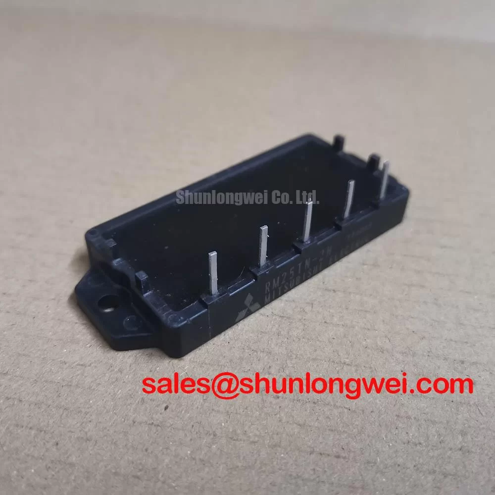
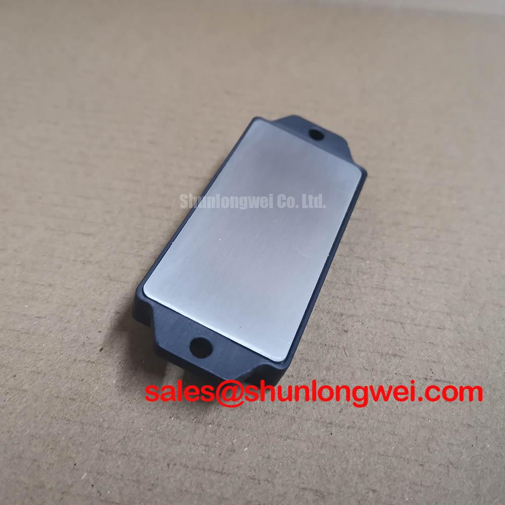
With the power isolated and the DC link discharged, verify the nameplate identity and inspect the RM25TN-2H terminals, case surface, and mounting face for damage, contamination, loose hardware, or signs of uneven heatsink contact before returning the assembly to service. The RM25TN-2H is identified as a Mitsubishi Electric diode module with an official rated voltage of 1200V and rated current of 25A. These are Official Datasheet Specifications and establish the electrical identity that must be matched against the existing rectifier circuit documentation.
For maintenance planning, treat the voltage and current ratings as device limits rather than complete system ratings. The DC link topology, fuse coordination, transformer secondary characteristics, ambient conditions, heatsink condition, and actual current waveform determine whether the installed assembly operates within acceptable thermal and electrical boundaries. Before replacing a module in a high current DC rectifier, maintenance personnel should compare the original circuit connection, polarity marking, mechanical footprint, and approved equipment documentation.
| Parameter | Value | Status |
|---|---|---|
| Model | RM25TN-2H | Official product identification |
| Manufacturer | Mitsubishi Electric | Official manufacturer identification |
| Rated voltage | 1200V | Official Datasheet Specification |
| Rated current | 25A | Official Datasheet Specification |
| Package classification | Diode Module | Official structured product information |
RM25TN-2H Thermal-Electrical Optimization: Thermal Interface Material Spreading Across Practical Tuning
Begin the installation check at the mounting interface, because a diode module can only transfer internally generated heat into the heatsink when its contact face is clean, flat, and uniformly supported. Remove old thermal compound carefully, inspect the heatsink for raised burrs or embedded debris, and check whether previous compound distribution indicates a full contact pattern. A patchy transfer pattern can point to contamination, distorted hardware, uneven clamping, or a heatsink surface issue that deserves correction before a replacement module is fitted.
The specified 1200V and 25A ratings identify the RM25TN-2H electrically, but they do not provide a complete thermal installation prescription. Junction to case thermal resistance, approved mounting torque, allowable case temperature, surge ratings, and fuse coordination details should be taken from the applicable Mitsubishi Electric documentation for the exact assembly revision. Do not infer those values from another package or from a similarly rated device.
As a Design Consideration, spread an appropriate thermal interface material in a controlled, thin, continuous layer that fills surface irregularities without creating isolated heavy deposits. Tighten mounting hardware in a balanced sequence so the module settles evenly against the heatsink. The final torque must follow the approved mechanical documentation for the installed hardware and module. Excessive fastening force can distort a housing or damage threads, while inadequate force can leave local thermal resistance high.
Cooling work should also include the wider heat path. Inspect fan operation, air filters, duct seals, fin blockage, cabinet recirculation paths, and signs of moisture or corrosion around the heatsink. In rectifier cabinets that cycle between cool standby and loaded operation, condensation control and enclosure sealing are part of preventive maintenance because surface moisture can affect insulation paths and terminal cleanliness. Maintenance Note: Monitor terminal and heatsink contact temperature during representative load operation, then correct blocked airflow or loose mechanical interfaces before they create repeatable thermal stress.
For a high current green hydrogen electrolyzer DC power rectifier, the RM25TN-2H should be evaluated as one component within a larger rectification path. The equipment owner should verify the actual current waveform, duty cycle, cooling arrangement, and upstream protection against the original system documentation. A module rated at 25A should never be assessed solely from a panel ammeter reading when current ripple or cyclic loading may be present.
Assembly Integrity & Layout Architecture: Implementing RC Snubber Network Optimization to Prevent Stress for RM25TN-2H
Before altering any suppression network, document the existing wiring route, terminal orientation, snubber connection points, capacitor markings, resistor condition, and evidence of overheating. The RM25TN-2H is a diode module, so gate drive terminology, gate damping values, and thyristor triggering instructions do not apply to this product. Its integration should instead focus on the rectifier topology, diode commutation path, reverse voltage exposure, protection arrangement, and the physical loop formed by the transformer, wiring, diode module, DC link, and any suppression components.
RC snubber networks are a Design Consideration at system level. Their purpose is typically to control voltage transient behavior associated with commutation and wiring inductance, but the appropriate component values depend on the measured waveform, circuit impedance, switching or commutation conditions, capacitor pulse capability, resistor energy capability, and the existing equipment design. Engineers should evaluate waveform behavior at the installed circuit and verify peak voltage margins against the 1200V Official Datasheet Specification during controlled tests.
Minimize parasitic loop inductance where transient overshoot must be suppressed, especially around the diode path and DC bus connection. Keep conductors appropriately routed, avoid unnecessary loop area, and ensure that a snubber connection has not become resistive through oxidation, vibration, or loose fastening. The final layout and suppression network must be validated by the system engineer using measured voltage and current waveforms, not assumed from a nominal diode current rating.
Fuse coordination is equally important during assembly review. The module’s rated current does not define a fuse selection by itself. The protection device must be assessed against the rectifier’s available fault current, source impedance, expected inrush behavior, semiconductor protection requirements, and the fuse manufacturer’s time current and energy data. Where a fuse I²t coordination table is required, use approved documentation for the installed fuse and the applicable module data rather than a generic table from another power semiconductor family.
Terminal integrity has practical consequences for both thermal and electrical performance. Check that busbars have correct alignment, that they do not apply side load to the module terminals, and that insulating barriers are restored after service. A discolored connector, cracked lug, or unstable torque witness mark does not establish one failure cause, but it warrants investigation of contact resistance, vibration exposure, cabinet heating, and the load history.
For comparison during an engineering review, RM500CZ-M can be examined as a separate module option only after its topology, electrical ratings, mechanical arrangement, and manufacturer documentation have been checked against the original circuit. Similar product naming or a higher current figure alone does not establish interchangeability.
Preventing Spurious Faults: Diode Peak Reverse Recovery Current and Switching Guidelines for RM25TN-2H
When a rectifier assembly exhibits recurring fuse operation, excessive electrical noise, or unexpected heating, inspect the diode commutation environment before assigning a cause to the module. Reverse recovery behavior is influenced by current, temperature, circuit inductance, source waveform, and the rate at which current transfers through the associated circuit. Peak reverse recovery current and recovery time are device specific characteristics that must be verified in the relevant official documentation; they should not be estimated from the 25A rated current.
A diode module does not use a gate circuit, so spurious gate turn on and gate pulse tuning are not applicable to RM25TN-2H. In a mixed power cabinet, it is still important to distinguish the diode rectifier section from adjacent controlled switches, braking choppers, contactors, or converter legs. This prevents a maintenance team from applying diagnostics intended for an IGBT or thyristor device to an uncontrolled diode rectifier position.
As a Design Consideration, use an oscilloscope and appropriately rated measurement method to compare the suspected commutation path with a known good path where available. Observe the relationship among line current, DC bus voltage, transient ringing, and the operating condition that produces the event. A waveform with ringing may indicate a layout or suppression issue, but it can also reflect probe setup, source impedance, connection condition, or another part of the power assembly. Verify the complete path before replacing protection components or changing circuit values.
EMI compliance is a property of the finished equipment, its enclosure, wiring, filters, operating state, and test arrangement. The RM25TN-2H should not be represented as independently compliant with an equipment level EMC standard. When industrial equipment requires corrective action, maintenance teams should return to the approved system configuration and assess cable shielding, grounding continuity, filter condition, wiring geometry, and suppression hardware under the equipment’s documented test requirements.
Mitsubishi Electric provides product family context through its Global Semiconductor Device Technologies information and its Power Semiconductors and High Power Modules resources. For system level reliability discussions, the technical reference Future of Power Electronics can support broader evaluation, while the installed module must still be assessed from its exact documentation and measured operating conditions.
RM25TN-2H Circuit Protection & Reliability: Calibrating Non-Repetitive Surge On-State Current
After an overload, line disturbance, or rectifier protection event, isolate the equipment and establish whether the diode module was exposed to abnormal current, reverse voltage, inadequate cooling, or a downstream DC bus fault. Do not assume that a visible fuse operation identifies the failed component or confirms that the module is unusable. Inspect the associated transformer connections, busbars, capacitors, suppression network, load circuit, cooling system, and protection devices before restoring power.
Non repetitive surge current is a specific datasheet characteristic, often associated with defined test conditions such as a sinusoidal half cycle. No RM25TN-2H surge current value is stated here because it must be taken directly from the applicable official Mitsubishi Electric datasheet. A maintenance decision should also account for the relevant starting junction condition and the subsequent operating conditions before another surge event. Those conditions are system dependent and must not be replaced with an assumed time or generic multiplier.
For green hydrogen electrolyzer DC power rectifier maintenance, check whether a process upset created abnormal current demand, whether transformer phase balance remains correct, and whether the DC load has developed a low impedance condition. The rectifier’s actual duty, current sharing arrangement, and upstream protective coordination determine the electrical stress seen by each diode path. When integrating or replacing the RM25TN-2H, designers should verify polarity, circuit location, cooling interface, insulation clearances, and all protection settings against the original equipment records.
Preventive work should include periodic heatsink cleaning, inspection of aged thermal interface material, confirmation of terminal fastening to the approved torque, and examination of cabinet seals where humid air or condensation is possible. Record the observed condition and measured operating temperatures over time. This creates a defensible maintenance history without inventing service life predictions, failure rates, or unverified reliability claims for the module.
The correct service boundary is clear: the RM25TN-2H Mitsubishi Electric diode module is identified by its 1200V and 25A Official Datasheet Specifications, while surge capability, thermal limits, fuse coordination, and transient control must be verified from the exact module documentation and the measured behavior of the finished rectifier system.