Content last revised on November 18, 2026
VHF28-12IO5 Identification and Bench Checks
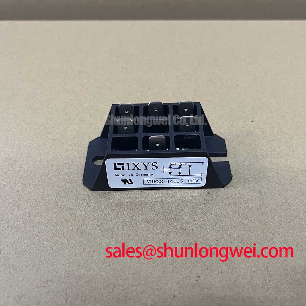
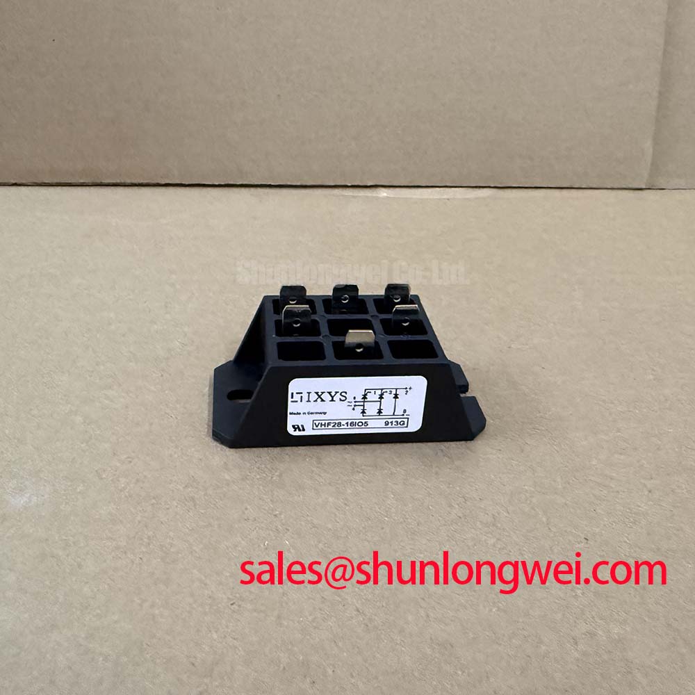
With the power stage isolated and stored energy discharged, map the terminal markings on the VHF28-12IO5 against the equipment schematic before taking diode-mode readings. Record probe polarity and compare corresponding conduction paths under the same cold conditions. A meter reading can reveal an unexpected conductive path, but it cannot establish reverse-blocking capability or demonstrate that a thyristor will trigger correctly under load.
The product specifications identify Manufacturer: IXYS, Part Number: VHF28-12IO5, Repetitive Peak Reverse Voltage (VRRM): 1200.0 V, and Average On-State Current (IT(AV)): 28.0 A. The specified Package: VUO/VUB Case and Configuration / Topology: Thyristor / Diode Module establish the identification baseline for this bridge rectifier module. These ratings are product specifications, not substitutes for the circuit diagram, rating conditions, or terminal drawing.
💡 Bench Tip: Keep gate connections under appropriate ESD control and compare cold readings with a known-good reference using identical meter polarity and test conditions.
VHF28-12IO5 Operational Boundaries: Evaluating Semiconductor Protection Fuse Selection
Compare the candidate semiconductor fuse’s total clearing I²t with the module’s applicable withstand I²t at the relevant fault duration and initial junction temperature. As a Design Consideration, this comparison belongs in a coordination record that also captures prospective fault current, circuit voltage, fuse breaking capacity, and the manufacturer’s correction conditions. A fuse’s continuous current rating alone does not establish semiconductor protection.
For the VHF28-12IO5, the procurement and test file should retain the manufacturer’s surge-current and I²t data alongside the selected fuse curves. Consult the datasheet for surge limits, gate limits, thermal resistance, insulation test conditions, and mounting and terminal torque. Distinguish total clearing I²t from pre-arcing I²t when reviewing fuse tables; otherwise, a comparison can omit the contribution while the fuse arc persists. Coordination reduces damage risk but cannot guarantee damage-free interruption of every short circuit.
Trace each power terminal to the schematic before reconnecting buswork. During incoming inspection, an unusual diode-mode result warrants separating the module from parallel resistors, snubbers, and other semiconductor paths before repeating the measurement. Do not interpret an untriggered thyristor’s blocking state as proof of an open-circuit defect.
When comparing the VVZ24-12IO1, treat it as a separate candidate rather than an established direct replacement. Compatibility requires agreement on circuit arrangement, terminal positions, current-rating conditions, gate requirements, mechanical fit, and protection coordination. Procurement records should preserve the full part designation rather than approving a replacement from voltage class alone.
Transient Dynamics & Electrical Design: RC Snubber Network Optimization for VHF28-12IO5
Measure voltage transients across the relevant semiconductor terminals with a suitably rated differential measurement arrangement before changing the RC snubber. As a Design Consideration, the capacitor influences transient voltage rise, while the resistor controls damping and discharge current. Select their values through circuit analysis and representative switching measurements, checking repetitive voltage, pulse energy, component temperature, and measurement-loop artifacts.
Keep the snubber current path compact to limit additional inductive overshoot, while maintaining the electrical spacing required by the equipment design. If the existing circuit includes a series saturable reactor, evaluate its current-rise control, reset behavior, and heating together with the commutation waveform. Adding or changing a reactor without this assessment can alter the operating sequence rather than simply improve protection.
At the gate connection, compare the delivered pulse with the specified trigger current and voltage conditions, including the return path and operating temperature. Pulse-train triggering should be assessed against permitted gate power and the equipment’s firing sequence; stronger triggering is not an unrestricted remedy for unreliable conduction. Correlate missed firing with gate-terminal measurements before attributing it to the module.
For surrounding conductors carrying substantial high-frequency ripple, proximity effect in high-frequency magnetics and transformers explains why current distribution can increase AC losses. This is relevant to external conductors and magnetic components, not evidence of a particular internal construction in the VHF28-12IO5.
Assembly Integrity & Layout Architecture: Thermal Interface Material Application for VHF28-12IO5
Inspect the heatsink contact surface for contamination, burrs, and uneven witness marks before applying thermal interface material. As an Engineering Recommendation, use the interface material and application method specified for the assembly, spreading it consistently without treating excess paste as a remedy for poor flatness. Follow the module’s fastening sequence and torque requirements, keeping mounting screws distinct from electrical terminal fasteners.
Evaluate junction-to-case thermal resistance separately from the case-to-heatsink interface. Uneven contact pressure, distorted mounting surfaces, or busbar loading can compromise the external thermal path even when the semiconductor’s rated thermal resistance is unchanged. Support conductors so terminal tightening does not force the housing against a misaligned assembly.
Check clearance and creepage around terminals against the equipment’s working voltage, pollution conditions, and applicable insulation requirements. The 1200.0 V reverse-blocking rating is not an insulation test voltage. Perform insulation testing only with the prescribed terminal grouping, test conditions, and isolation of sensitive connected circuitry.
When evaluating a medium-frequency induction melting or hardening furnace rectifier stage, match the actual schematic and cooling arrangement to the VHF28-12IO5 product identification. For broader power-stage integration context, the Power Backbone engineering guide provides supplementary discussion rather than model-specific lifetime evidence. Record contact condition, fastener settings, terminal mapping, and thermal observations so subsequent maintenance comparisons use a reproducible assembly baseline.