


Content last revised on September 11, 2026
Transient Dynamics & Electrical Design: Baseplate Convexity Compensation and Screw-On SEMIX223GD12E4C
| Manufacturer | SEMIKRON |
|---|---|
| Product Category | IGBT Module |
| Part Number | SEMIX223GD12E4C |
| Official Voltage Rating | 1200V VCES |
| Official Current Rating | 225A IC |
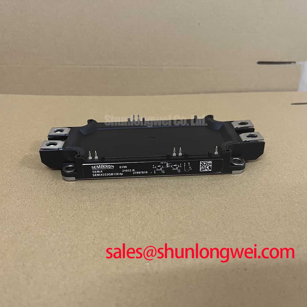
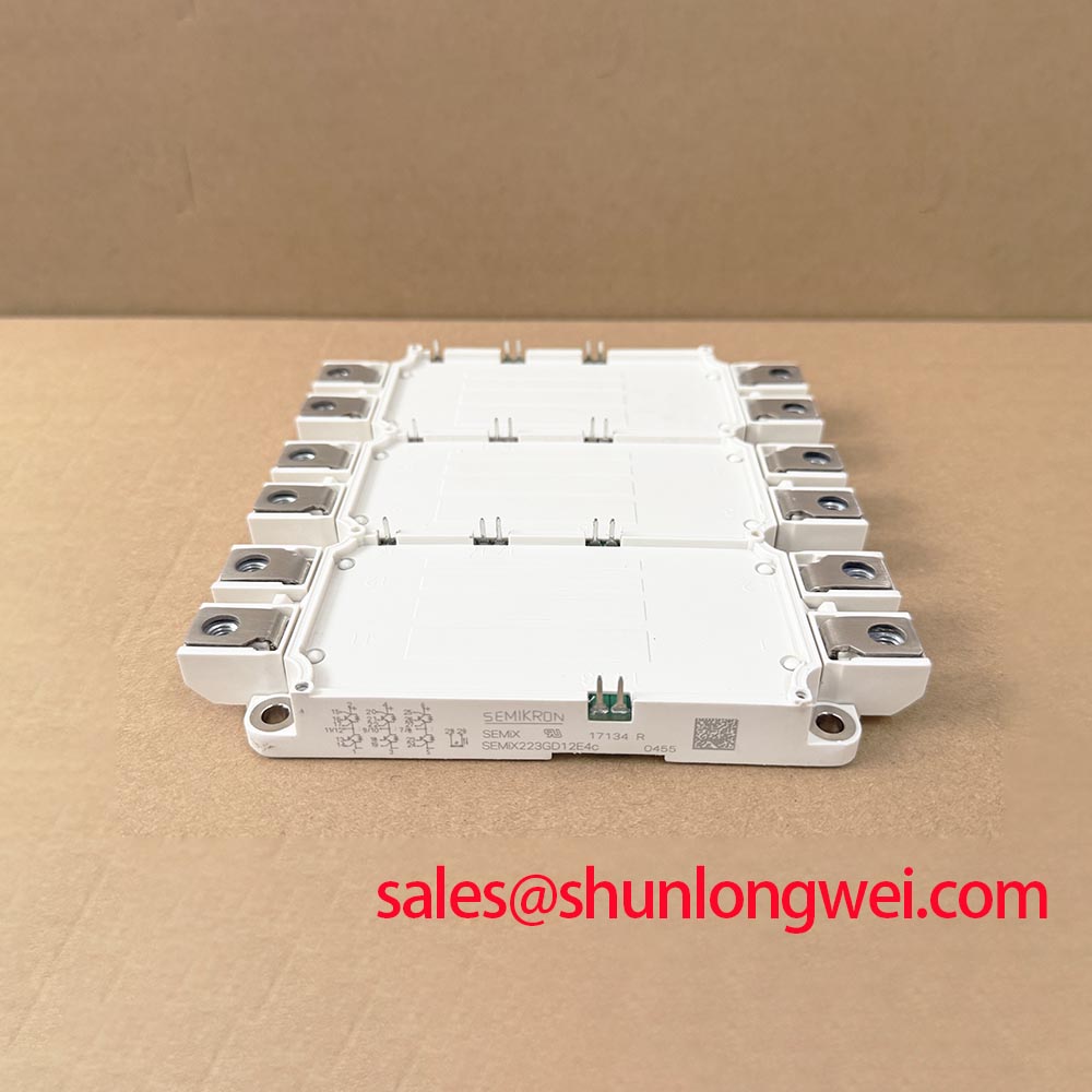
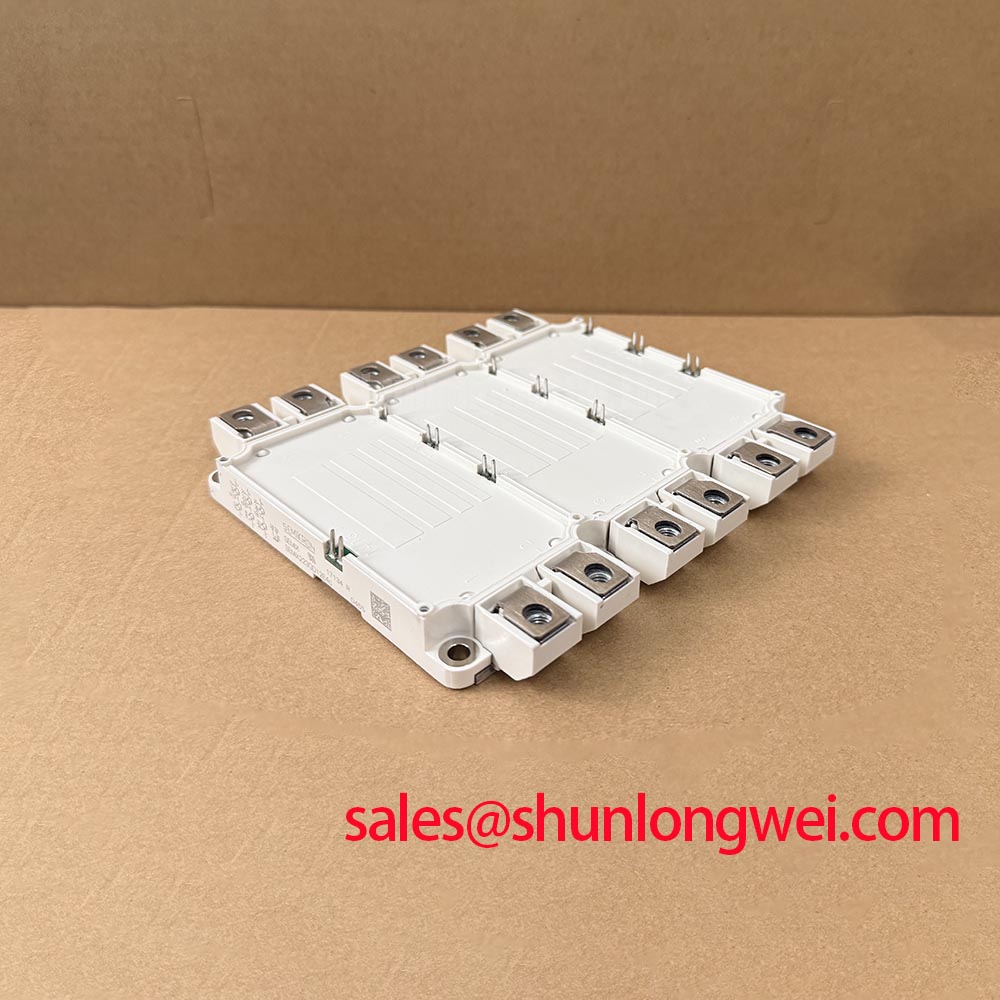
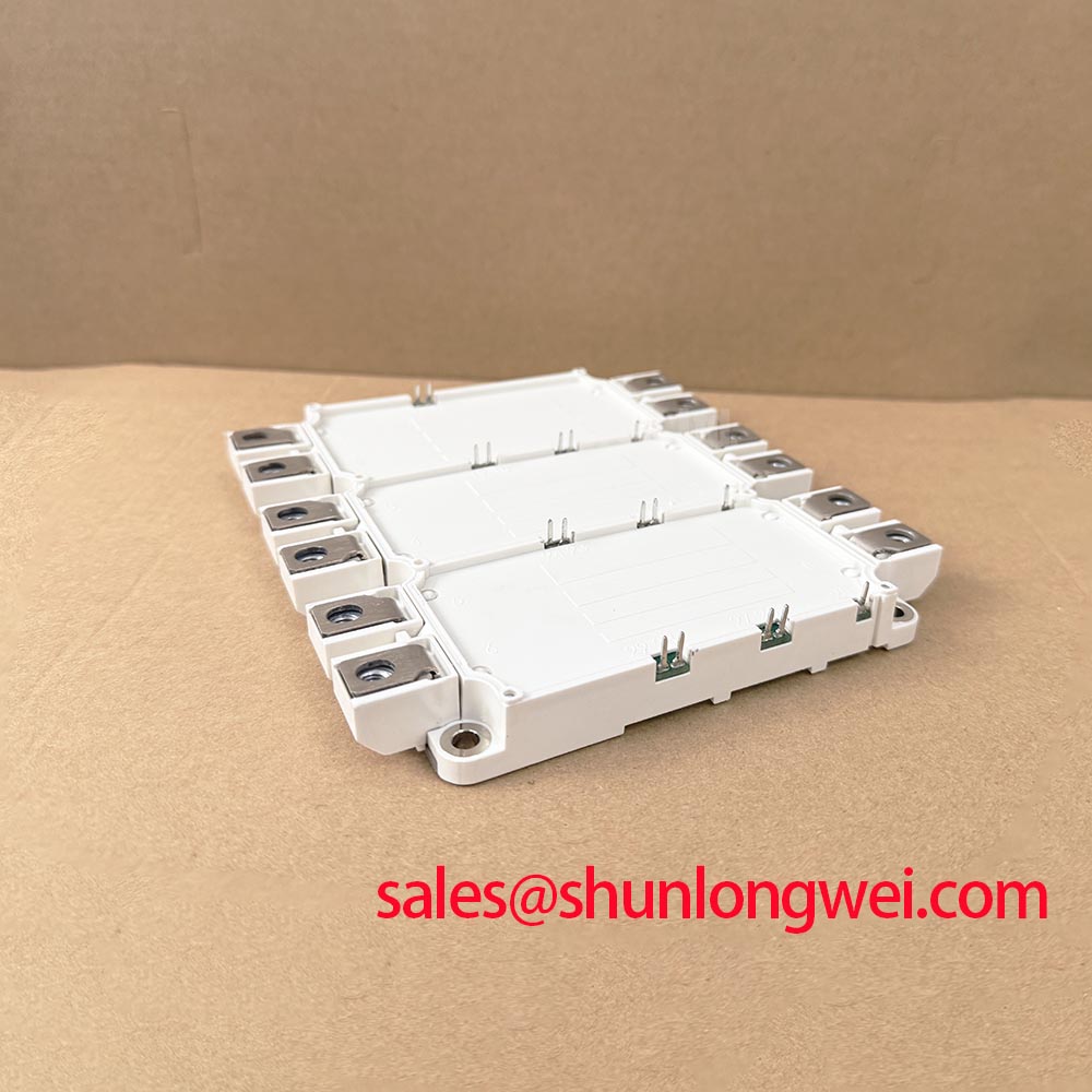
| Package | SEMiX 3p Sixpack IGBT Module |
| Topology | General Power Stage |
| Series | Standard |
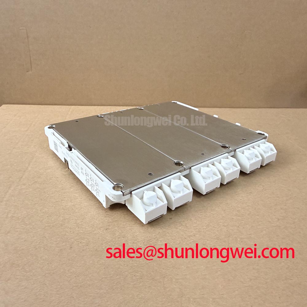
Check the cold baseplate surface and mounting face for visible burrs, trapped debris, corrosion residue, or uneven thermal compound before fastening the SEMIX223GD12E4C into the heatsink assembly. A module can pass static diode checks yet experience unstable thermal transfer if the contact plane is distorted or clamped unevenly. This is especially relevant when replacing a power stage in a forklift traction inverter that has previously experienced vibration, repeated temperature cycling, or a damaged cooling fan.
The module is officially rated at 1200V VCES and 225A IC. Those ratings identify the electrical boundary of the semiconductor module, but they do not eliminate the need to inspect the mechanical heat path. Design Consideration: apply thermal interface material as a thin, continuous layer across the intended contact area, controlling thickness within the practical range needed to fill machining marks without creating an insulating layer. A common assembly starting range is 50 to 100 μm, subject to the heatsink flatness, interface material type, and the equipment manufacturer’s assembly requirements.
When the heatsink face has slight curvature, uncontrolled fastening can pull one area of the module down first while leaving another area poorly coupled. Use a progressive cross pattern across the available mounting points, increasing clamp load gradually and checking that the module remains seated evenly. Do not use terminal hardware to draw the package toward the heatsink. Terminal screws establish electrical connection; mounting hardware establishes the thermal and mechanical interface.
💡 Bench Tip: Keep the module and gate drive harness disconnected from stored DC link energy while performing cold resistance and diode mode comparisons against a known good assembly.
Use a meter in diode mode only as a comparative incoming inspection method. With the gate connections held in their intended inactive state, compare the expected directional behavior between each power path and its associated freewheeling diode path according to the inverter connection drawing. An unexpectedly conductive path in both directions, a direct short between main terminals, or a major difference from a verified matching module can justify further isolation before installation. A diode mode result alone does not prove dynamic switching health.
For broad device selection context, including the engineering role of IGBT modules in power conversion equipment, see THE-IGBT-THE-CPU-OF-THE-ELECTRONIC-POWER-INDUSTRY. Any cross model evaluation should still verify package footprint, terminal arrangement, topology, gate driver compatibility, cooling interface, and protection thresholds at the system level.
Benchtop Waveform Tuning: Mitigating Stress via Isolated DC-DC Power Supply Sizing for SEMIX223GD12E4C
Probe the gate to emitter waveform at the module connection point while the inverter is operating at controlled load, then compare the intended switching command with the waveform actually reaching the SEMIX223GD12E4C. A clean controller side pulse does not guarantee a clean gate waveform at the module when the isolated driver supply, return routing, or common mode behavior is inadequate. Observe both the commanded turn on and turn off events, particularly while the opposite switch position commutates current.
The isolated DC-DC supply serving a gate driver must support the driver’s operating demand without allowing supply disturbance to alter gate command integrity. Engineering Recommendation: verify galvanic isolation capability and common mode transient immunity against the measured switching environment of the complete inverter, rather than treating generic isolation claims as proof of suitability. Spurious gate pulses can arise from return path movement, digital isolator behavior, optocoupler recovery characteristics, or coupling between power conductors and control wiring.
The SEMiX 3p sixpack arrangement places a complete general power stage in one module package, making consistent phase leg timing and low noise drive routing important during service work. Route each gate command and its corresponding return as a close pair. Keep those control paths separated from high current collector and emitter conductors wherever the inverter construction allows. If the applicable terminal arrangement includes an auxiliary emitter reference, use it only according to the verified connection information for the installed driver board and module configuration.
Freewheeling diode reverse recovery can contribute to switching current stress and radiated noise. A sharp recovery waveform may be associated with ringing or high frequency emissions, but it should be diagnosed with voltage and current measurements rather than assumed from audible noise or visible waveform ripple. Design Consideration: investigate gate resistance balance, local decoupling condition, busbar geometry, and snubber network condition together. A failed or disconnected snubber capacitor can change the observed waveform significantly without indicating an internal module fault.
For systems where the traction inverter is supplied through an isolated power architecture, the role of a DRY-TYPE-ISOLATION-TRANSFORMER can be assessed as part of the wider input power arrangement. Transformer selection, rectification, DC link energy storage, grounding method, and gate driver isolation all remain system determined matters rather than characteristics guaranteed by this IGBT module.
Use an oscilloscope probe arrangement with suitable bandwidth, voltage rating, and reference method for the measured node. A long ground lead can add measurement loop inductance and present ringing that is partly created by the probing arrangement. Recheck unusual turn off peaks with an appropriate differential measurement method before changing the gate drive or overvoltage suppression network.
Assembly Integrity & Layout Architecture: Implementing Turn-Off di/dt-Induced Vpeak Clamping for SEMIX223GD12E4C
Measure the DC link voltage and the switching node at turn off under controlled operating conditions, then compare the observed peak with the module’s 1200V VCES boundary and the protection behavior of the inverter. The switching peak is governed by the DC link level plus the voltage generated by stray inductance and changing current, commonly described in engineering analysis as Vpeak being VDC plus Lσ multiplied by di/dt. This relationship is an Engineering Calculation principle, not an official switching limit for the module.
Design Consideration: minimize the physical loop formed by the DC link capacitor, module power terminals, and commutation path to suppress inductive overshoot during turn off. Symmetrical laminated or planar busbar routing is often evaluated because it can reduce loop area and help maintain more consistent phase behavior. The required layout performance must be verified on the actual inverter with its operating current, cable routing, cooling arrangement, DC link capacitor placement, and switching strategy.
Inspect busbar faces, terminal washers, screw seating, and capacitor connections for evidence of heat discoloration, looseness, or fretting. A mechanically sound connection can still present an electrically poor interface if oxide films or contamination remain between conductive surfaces. Clean and reassemble using the equipment manufacturer’s specified hardware sequence. Maintain appropriate creepage and clearance around energized conductors according to the system voltage, pollution environment, enclosure condition, and applicable equipment standards.
A metal oxide varistor and RC snubber can be part of a coordinated overvoltage control approach, yet neither should be treated as a universal corrective action. The MOV operating condition, energy absorption capability, placement, and coordination with fuse protection are determined by the equipment design. Snubber capacitor selection likewise depends on measured ringing frequency, allowable loss, voltage exposure, and thermal conditions. Replace damaged suppression parts with verified equivalents from the original system design rather than selecting values by visual similarity.
Where elevated DC link voltage, regeneration, or fast commutation is present, engineers can use Peak Efficiency in Solar and Energy Storage as a reference for broader inverter topology evaluation. It is useful for studying switching architecture, but it does not replace bench verification of the installed SEMIX223GD12E4C power stage.
The official manufacturer’s wider power semiconductor portfolio is available through the Semikron Danfoss Power Electronics and Modules Official Hub. Product family comparisons should not be used to infer identical electrical behavior, pin assignment, thermal interface, or protection requirements for this specific module.
Preventing Spurious Faults: Dynamic Power Loss Dissipation and Multi-R Guidelines for SEMIX223GD12E4C
Capture the fault event together with phase current, DC link voltage, gate command, and heatsink temperature trend before attributing a shutdown to the SEMIX223GD12E4C. A protection trip during acceleration, lifting, or regenerative deceleration may involve current sensing, driver desaturation detection, DC link movement, cooling performance, control timing, or power stage switching behavior. Correlating several signals avoids treating one symptom as proof of one failure mechanism.
The module’s thermal response to repetitive pulses is not represented by a single steady state temperature figure. Design Consideration: use the applicable transient thermal impedance information and a multi-R thermal model when the equipment design requires pulse load analysis. Such a model represents heat flow through several time dependent thermal paths, allowing the system engineer to compare pulse energy, repetition pattern, case temperature, and measured cooling performance against the permitted operating conditions.
For repair work, inspect the heatsink air path, coolant circuit where fitted, fan operation, thermal compound coverage, and clamping consistency before changing the power module. A blocked airflow path or degraded pump may raise case temperature slowly, while a poor interface may produce more localized thermal stress. Neither condition can be reliably diagnosed from a static resistance measurement alone.
In electric material handling and forklift low voltage traction systems, this 1200V, 225A SEMIKRON module can be evaluated for an inverter power stage only after confirming the existing topology and control arrangement. Check that each phase leg connection, driver channel, current sensor reference, DC link capacitor path, and motor cable termination remains consistent after service. Replacing a module without checking these surrounding interfaces can leave the original fault mechanism active.
Use controlled load testing after assembly and monitor whether the three phase waveforms remain balanced through acceleration and deceleration. If one phase shows abnormal switching behavior, isolate the driver board channel, gate wiring, suppression network, and terminal contact condition before judging the module itself. For related compact power module product context, consult Semikron MiniSKiiP Power Modules; this reference does not establish interchangeability with the SEMiX 3p package.