


Content last revised on June 18, 2026
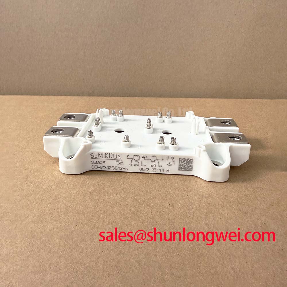
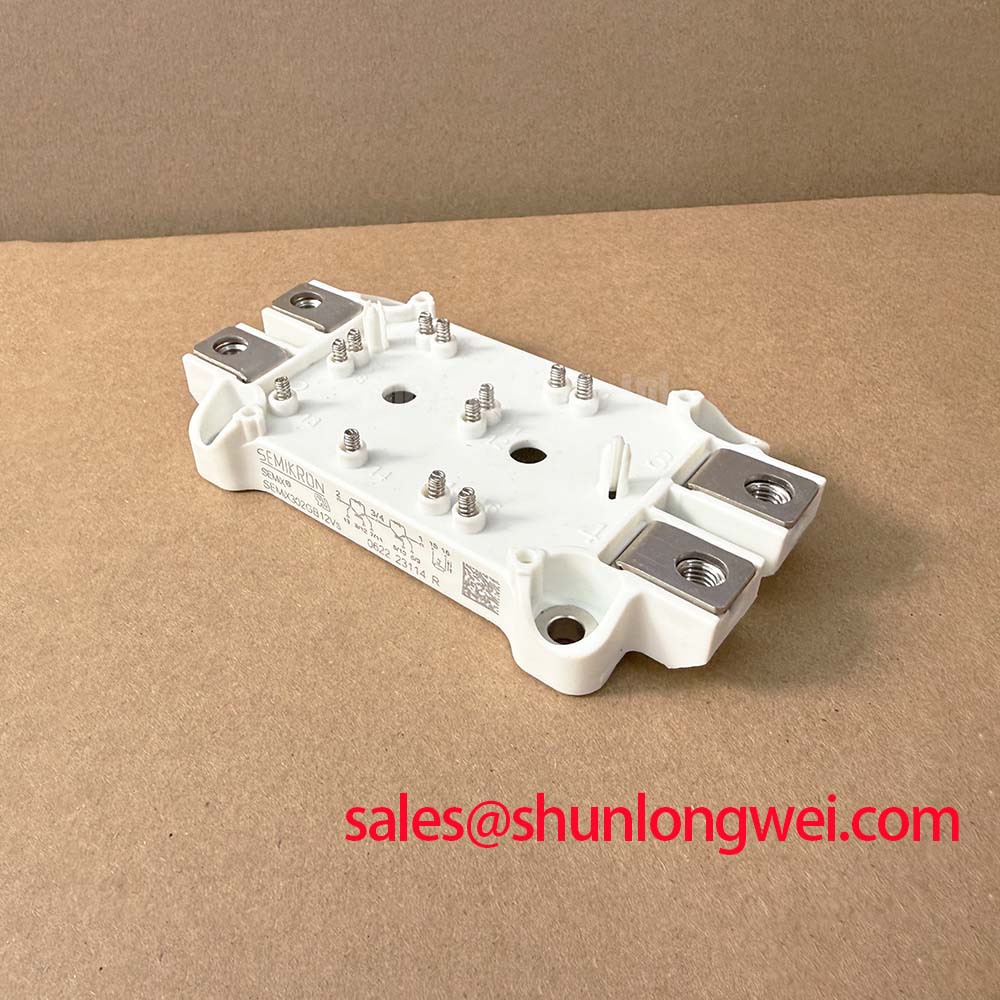
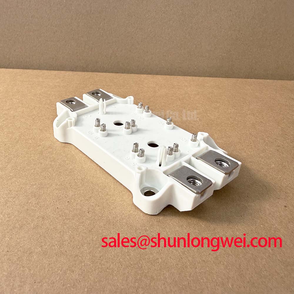
SEMiX302GB12Vs Semikron 1200V 300A Half-Bridge IGBT Module
The SEMiX302GB12Vs represents a high-performance half-bridge IGBT Module solution designed by Semikron to bridge the gap between high power density and long-term mechanical reliability. Utilizing advanced Trench IGBT 3 technology, this module is optimized for low switching losses and robust thermal performance in demanding industrial environments. For 400V AC motor drives requiring high power density and solderless reliability, the SEMiX302GB12Vs is the optimal half-bridge choice.
Key Highlights:
- 1200V | 300A (Ic nom) | Vce(sat) 1.70V (typ.)
- Advanced Trench IGBT technology for reduced conduction losses.
- Integrated solderless spring contacts for gate and auxiliary connections.
What defines the SEMiX302GB12Vs's efficiency? Its Trench IGBT technology minimizes switching losses significantly. Why use spring contacts? They ensure reliable connections and faster assembly without soldering gate pins. This module effectively addresses the challenge of thermal fatigue in high-duty cycle applications through its optimized copper baseplate and Safe Operating Area (SOA) characteristics.
Application Scenarios & Value
Achieving System-Level Efficiency in High-Power Inverter Topologies
Engineers often face the dual pressure of increasing power output while shrinking the physical footprint of Variable Frequency Drive (VFD) and UPS systems. The SEMiX302GB12Vs solves this by offering a high 300A current rating in a compact SEMiX 3s package. In a UPS application, the module's low Vce(sat) of 1.70V at 300A directly translates to lower heat dissipation, allowing for smaller heatsinks and higher efficiency ratings.
In renewable energy systems, such as solar central inverters, the 1200V rating provides a necessary safety margin for DC-link voltages common in 400V-480V grid-tied systems. The module's high short-circuit withstand time of 10µs provides a critical window for Gate Drive protection circuits to intervene during fault conditions, preventing catastrophic failures. For systems requiring even higher current handling, the related SEMIX453GB12VS offers a Vces of 1200V with significantly higher amperage capability.
The integration of the CAL Diode (Controlled Axial Lifetime) as a freewheeling diode further enhances its value in motor drive applications. This diode features soft-switching characteristics and low reverse recovery charges, which are essential for reducing electromagnetic interference (EMI) and voltage spikes during high-frequency switching. This makes the SEMiX302GB12Vs an excellent choice for Servo Drive units where precision and noise suppression are paramount.
Technical Deep Dive
Analyzing Trench IGBT 3 Physics and Solderless Interconnect Reliability
The core of the SEMiX302GB12Vs is the Trench IGBT 3 chip architecture. Unlike older planar structures, the trench design creates a vertical gate channel, which increases cell density and reduces the on-state resistance. To visualize this: Vce(sat) is like the resistance of a pipe; a lower value means less pressure (energy) is lost as the current flows through. This lower resistance minimizes the conduction losses that typically dominate at lower switching frequencies.
Thermal management is the second pillar of this module's design. The Thermal Resistance (Rth(j-c)) for the IGBT part is rated at 0.11 K/W. Using another analogy: Rth is like a thermal highway; the lower the resistance value, the wider and smoother the highway, allowing heat to escape from the silicon junction to the baseplate more rapidly. This superior heat transfer capability allows the module to operate at a continuous junction temperature of up to 150°C (and 175°C during switching transients), providing a generous buffer for peak load conditions.
The SEMiX 3s housing is specifically designed for Semikron SKiiP® Technology-inspired assembly. By utilizing spring contacts for signal pins, the module eliminates solder joints between the PCB and the IGBT, which are common failure points in high-vibration or high-temperature cycling environments. This solderless interconnect technology increases the Power Cycling Capability of the system, a critical factor for industrial machinery that undergoes frequent start-stop cycles.
Key Parameter Overview
Functional Specification Analysis for Thermal Management Optimization
| Category | Parameter | Value / Condition |
|---|---|---|
| Maximum Ratings | Collector-Emitter Voltage (Vces) | 1200V |
| Collector Current (Ic) @ Tc=80°C | 236A (300A @ 25°C) | |
| Short Circuit Withstand Time | 10µs @ Vge=15V | |
| Electrical Specs | Saturation Voltage Vce(sat) | 1.70V (typ. @ Tj=25°C) |
| Gate Threshold Voltage Vge(th) | 5.8V (min. 5V, max. 6.5V) | |
| Turn-on Energy (Eon) | 30mJ (typ. @ 300A, 600V) | |
| Thermal/Mech | Thermal Resistance Rth(j-c) | 0.11 K/W (IGBT) |
| Weight | 300g |
Download the SEMiX302GB12Vs datasheet for detailed specifications and performance curves.
Frequently Asked Questions
How does the Rth(j-c) of 0.11 K/W directly impact heatsink selection and overall system power density?
A low Rth(j-c) of 0.11 K/W means the SEMiX302GB12Vs can dissipate heat more efficiently. This allows design engineers to either use a smaller, less expensive heatsink while maintaining safe Junction Temperatures, or drive the module at higher currents within the same thermal footprint, thereby increasing the system's power density.
What are the primary benefits of the "Vs" version (Trench 3) compared to older planar IGBT technologies?
The "Vs" suffix denotes the use of Trench IGBT 3 chips. These offer a significantly lower Vce(sat) and more efficient switching characteristics compared to planar modules. For the engineer, this means reduced energy losses and improved efficiency, especially in high-current industrial inverter applications.
Are there specific mounting considerations for the spring-contact interface in the SEMiX 3s package?
Yes. The spring-contact system requires a specific pressure to ensure electrical integrity. Engineers must follow the manufacturer's torque and PCB thickness guidelines to ensure the springs are correctly compressed. This solderless method eliminates the thermal stress associated with soldering large IGBT Modules to a PCB. For field diagnostics, refer to our guide on how to test an IGBT module with a multimeter.
To deepen your understanding of how these components integrate into broader power systems, we recommend exploring our analysis on IGBT module selection for high-efficiency systems. For technical procurement and project-specific technical data support, our team is available to assist with engineering-level documentation.