

Content last revised on September 18, 2026
SK45GH063 Inspection and Key Specifications
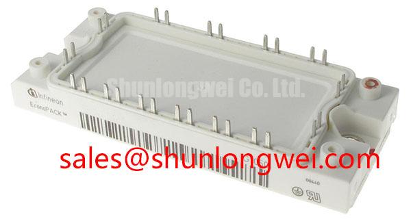
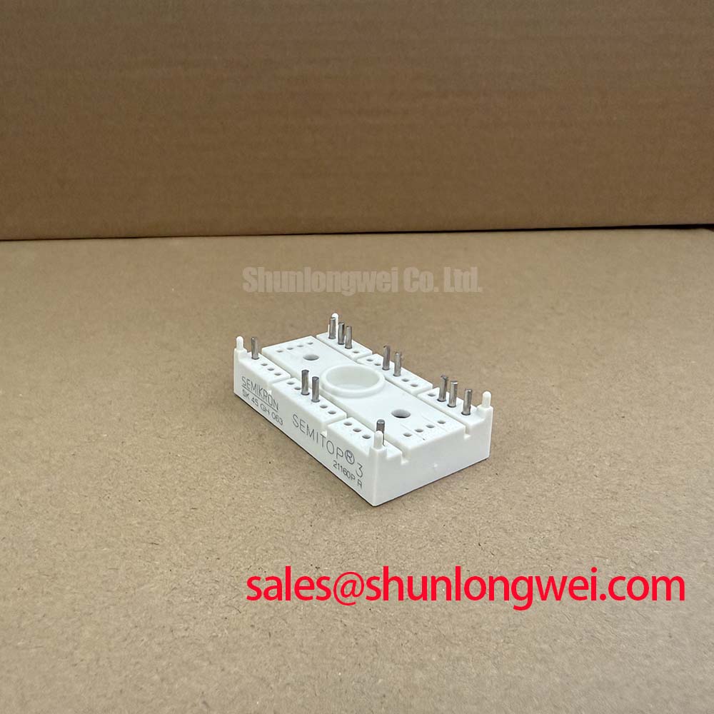
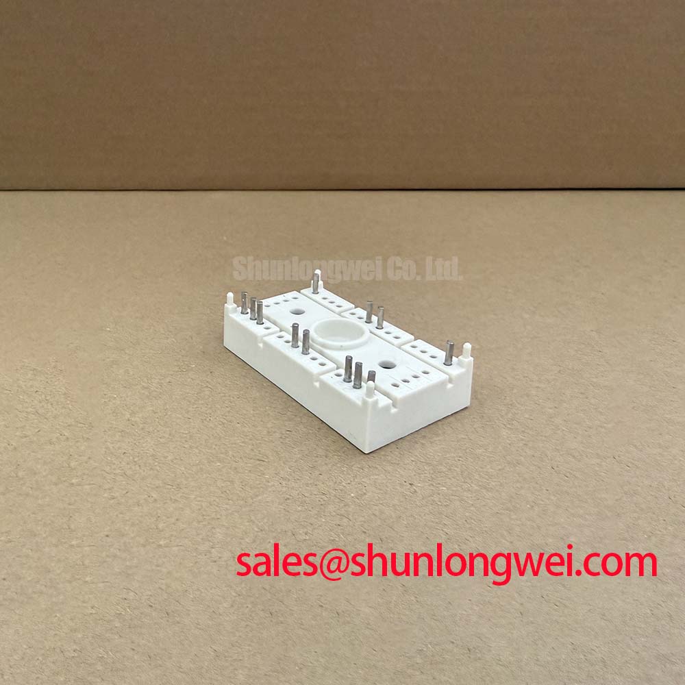
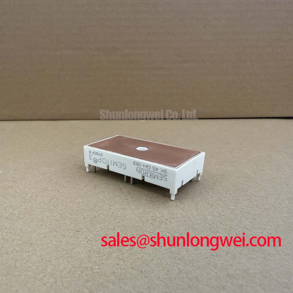
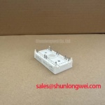
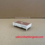
Start the bench check with the equipment isolated, then verify the nameplate against SK45GH063, measure the disconnected power terminals for abnormal low resistance, and inspect the Semitrans housing for cracks, loosened terminals, or heat discoloration. The confirmed product data identifies this Semikron power module as an IGBT Module rated at 600 V and 45 A. These are official product specifications supplied for this listing; gate-drive, switching-frequency, thermal-resistance, short-circuit, and surge-current values must be confirmed from the applicable manufacturer documentation before a replacement is energized.
| Parameter | SK45GH063 Specification | Engineering Use |
|---|---|---|
| Manufacturer | Semikron | Confirm the installed control and power-stage documentation before substitution |
| Device category | IGBT Module | Evaluate as a controlled switching element in the original topology |
| Voltage rating | 600 V | Compare with the measured DC-link voltage and switching overshoot |
| Current rating | 45 A | Check load current, pulse duration, cooling, and operating duty together |
| Package | Semitrans | Verify mechanical footprint, terminal arrangement, insulation, and heatsink interface |
SK45GH063 Circuit Protection & Reliability: Calibrating Dynamic Braking Chopper Operation
In an industrial inverter welder or medium-frequency induction heating supply, a braking chopper can become active when motor or load energy returns to the DC link. The first field task is to identify whether the original assembly uses this Semikron module in a braking path, an inverter leg, or another switching position. The product category and the confirmed 600 V voltage rating do not by themselves establish the allowable DC-link operating point, pulse current, repetitive braking duty, or resistor energy capacity. Those conditions are determined by the complete converter design.
Before replacement, record the DC-link voltage during startup, no-load operation, load operation, and deceleration. An oscilloscope with a suitable differential probe is preferable for observing transient peaks because a handheld meter cannot capture switching overshoot. Inspect the braking resistor for cracking, darkened ceramic surfaces, loose mounting, or changed resistance after isolation and discharge. A resistor that has drifted or lost thermal contact can force the chopper to operate outside its intended duty even when the IGBT itself is correctly rated.
The resistor and switching device should be assessed as one energy path. Designers should calculate the returned kinetic or stored load energy, determine how often the braking event repeats, and verify the resulting junction and heatsink temperatures through testing. A higher current rating does not automatically provide a safe substitute if the gate-drive timing, pulse duration, commutation path, or cooling arrangement differs from the original design.
For a failed unit, compare the gate-to-emitter and collector-to-emitter behavior with a known-good assembly only after the DC link has been fully discharged. An unexpected low-impedance reading may indicate a shorted power die, a connected snubber path, or an unisolated measurement route, so disconnect parallel circuitry before drawing a device-level conclusion. Check fuse condition, precharge components, freewheel paths, current sensors, and gate-driver output before installing another module.
Where the system uses a separate front-end rectifier or complementary power stage, the neutral reference is important during diagnosis. Engineers may review the associated SKM75GAL063D as a related Semikron module for the rectifier section, but compatibility must be established from the circuit diagram, electrical ratings, terminal arrangement, and thermal design rather than from package appearance alone.
Preventing Spurious Faults: Dynamic Gate Impedance Control Guidelines for SK45GH063
Gate-drive verification should begin at the driver output and continue to the module terminals with the shortest practical measurement loop. Confirm the actual gate-emitter voltage waveform during turn-on, turn-off, steady-state conduction, and fault shutdown. The supplied product information does not specify gate threshold voltage, recommended gate resistance, gate charge, maximum gate voltage, negative-bias requirements, or a guaranteed common-mode transient immunity value. These values must not be inferred from the 600 V, 45 A ratings.
High collector-voltage transition rates can couple through the device capacitances and the physical gate loop. A design consideration is to keep the gate-drive return path closely associated with the power-device reference and to separate high-current commutation paths from sensitive control wiring. The system engineer should verify the result with a differential probe at the module pins, not only at the isolated driver output. A waveform that looks clean at the driver but rings at the module indicates an interconnect or reference problem requiring layout review.
Active Miller clamping, a negative turn-off bias, or a desaturation protection circuit may be appropriate in some converter architectures, but their voltage levels and timing are system-dependent. Do not apply a negative gate voltage or select a gate resistor solely from a generic IGBT rule. Verify the permitted gate-emitter range in the exact Semikron documentation, then test turn-on delay, turn-off delay, dead time, fault response, and cross-conduction margin under the intended bus voltage and load.
Switching frequency also affects thermal behavior. A module operating at a moderate current may still exceed its thermal capability if switching losses, hard commutation, poor heatsink contact, or restricted airflow are present. The applicable loss calculation should use the manufacturer’s switching-energy data for the actual gate resistance, collector current, junction temperature, and voltage conditions. If those values are unavailable, bench testing should be treated as a compatibility assessment rather than a rating confirmation.
When a replacement module produces an intermittent overcurrent or gate-driver fault, inspect the driver supply, isolation barrier, gate-loop continuity, emitter reference, and fault latch timing as a group. The symptom alone does not identify a single failed component. The Semikron-Danfoss Power Electronics & Modules Official Hub and the manufacturer’s power module technical resources provide the appropriate reference point for confirming device-family information.
Field Alert: Disconnect the DC link and verify the discharge condition before touching the gate-drive connector or removing the module; control-side isolation does not prove that the power terminals are safe.
Benchtop Waveform Tuning: Mitigating Stress via Planar Symmetrical Busbar Geometry on SK45GH063
When the bench test shows a collector-emitter spike during turn-off, begin by confirming probe bandwidth, probe grounding, sensor calibration, and the physical measurement location. A long ground lead can create a false ringing pattern. Measure as close as practical to the module power terminals and compare the waveform with the known-good machine configuration. The relevant relationship is that parasitic inductance and current-change rate add voltage above the DC-link level; the design team must calculate the peak and verify it against the device rating during switching tests.
Minimize the area of the commutation loop containing the module, DC-link capacitor, and return conductor. A symmetrical laminated or planar busbar arrangement can reduce magnetic coupling and unequal current paths, but the acceptable inductance is determined by the switching speed, current, voltage margin, insulation system, and mechanical construction. The system designer should measure or model the complete loop instead of treating a generic inductance target as an official specification of SK45GH063.
Snubber selection should follow the observed waveform rather than a nominal capacitor value. Check whether the ringing is produced by the module’s output capacitance, busbar inductance, capacitor lead inductance, diode recovery, or an improperly located clamp. A snubber placed far from the switching loop may have limited effect and can introduce additional circulating current. Validate capacitor pulse capability, resistor dissipation, clearance, creepage, and temperature under repeated operation.
For industrial inverter welders, inspect the high-current output path for loose laminated joints, oxidized contact surfaces, and unequal conductor lengths. For medium-frequency induction heating equipment, also check the relationship between the inverter bridge, resonant network, current transformer, and DC-link capacitor. A module that passes a static resistance check can still experience excessive dynamic stress when the resonant load is mistuned or when current commutation occurs outside the intended operating window.
System-level topology has a direct effect on waveform stress and thermal duty. The technical discussion in Resonant Topologies in Home Appliances can help engineers compare switching arrangements, while the final selection for an industrial converter must remain tied to the actual schematic, load profile, and measured waveform.
Preventing Spurious Faults: Optocoupler vs Digital Coreless Transformer Guidelines for SK45GH063
Isolation troubleshooting should compare the driver-side waveform, isolated receiver waveform, and module gate-emitter waveform under the same switching event. An optocoupler or digital isolation device is part of the gate-drive system, not a guaranteed feature of the IGBT module. The supplied SK45GH063 data does not specify an isolation-barrier voltage, common-mode transient immunity, propagation delay, or pulse-width distortion. The integrator must verify these parameters from the selected driver component’s safety and electrical documentation.
Optocoupler-based drivers can require careful attention to aging behavior, propagation-delay spread, supply decoupling, and output-current capability. Digital isolators or coreless-transformer drivers may provide different delay matching and transient performance, but the choice depends on the gate-drive architecture, isolation classification, fault response, and layout. Neither approach should be described as suitable solely because the module is rated at 600 V.
Keep the isolation barrier physically clear of high dv/dt copper, provide the creepage and clearance required by the system insulation design, and place local driver decoupling close to the driver pins. Confirm the reference potential on each side of the barrier during switching. If a false turn-on appears only under high load, compare the gate-emitter waveform with the collector-emitter transition and inspect the return-current path before changing the control logic.
For a direct replacement evaluation, verify the Semitrans mechanical envelope, terminal identification, mounting interface, heatsink flatness, electrical clearances, and gate-driver connection against the original assembly drawing. The 45 A rating is an official product parameter, not a guarantee of continuous operation at every switching frequency, heatsink temperature, or overload profile. Final acceptance should include controlled startup, load-step testing, protection verification, and thermal measurement within the equipment manufacturer’s operating limits.