Content last revised on October 6, 2026
SKD25-08 Operational Boundaries: Checking Voltage Stress and Damping
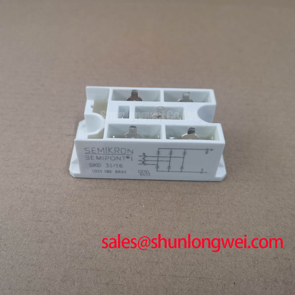
With the power isolated and the DC link discharged, check the SKD25-08 terminal markings against the equipment schematic before making a cold diode-mode measurement. This Semikron Semipont bridge rectifier module is listed with an 800 V voltage rating and is in the 25 A current class. Those ratings establish identification points, not permission to connect the module to an unverified circuit: terminal assignment, cooling conditions and protection coordination still need to match the installation.
Start with the rectifier’s job in the schematic. Identify the AC inputs and DC outputs from the original terminal drawing, then trace the path from the supply through the bridge to the DC link. Do not infer polarity from the position of a terminal or from a similar-looking Semipont unit. A diode bridge conducts according to applied polarity; it has no gate terminals to command and no firing-delay setting. Establishing that distinction at incoming inspection prevents a controlled-rectifier procedure from being applied to the wrong device.
The 800 V rating is an Official Specification for the listed SKD25-08. For a repair assessment, compare it with the voltage the bridge can encounter at its terminals, including supply variation and measured transients. The module’s current rating requires its specified reference temperature and cooling conditions to be interpreted correctly. Treat the current class as an identification and screening parameter until the applicable Semikron documentation establishes how it relates to the equipment’s heatsink and load cycle.
Design Consideration: An RC snubber can be evaluated where wiring inductance and diode commutation produce excessive terminal-voltage peaks. Its resistor and capacitor values are system-dependent; select them from measured waveforms, component stress limits and the existing equipment design rather than from the module’s voltage rating alone. A series reactor, if present in the original circuit, also needs assessment as part of that circuit. Neither accessory changes the bridge’s stated voltage limit.
On the bench, examine the mounting surface, fasteners and power connections for damage or looseness before energization. Use the mounting instructions for the exact module variant and heatsink assembly to determine tightening torque; no SKD25-08-specific torque value is provided in the supplied data. The Semikron-Danfoss power electronics hub is an appropriate manufacturer reference when obtaining documentation for a particular part and revision.
Transient Dynamics: Reading SKD25-08 Commutation Waveforms
A static diode-mode reading checks whether each accessible diode path conducts in the expected direction. Record probe polarity and the instrument reading for each path, then compare corresponding paths and a known-good assembly where available. A forward reading by itself does not establish that a diode will behave correctly under operating current or during commutation. An unexpected result warrants a repeat measurement with external wiring disconnected, because connected capacitors, parallel paths and test-lead contact can obscure the module reading.
💡 Bench Tip: Keep the bridge isolated during cold measurements and log both probe orientation and the meter model so a later technician can reproduce the comparison.
When the rectifier is operating in a suitable controlled test setup, observe voltage across the relevant bridge terminals and current in the commutating path. Reverse-recovery peak current and recovery time are useful quantities for evaluating switching stress, but no SKD25-08 values for them are included in the supplied product data. They should not be presented as factory limits or inferred from another bridge. Compare the captured behavior with the applicable manufacturer data and the equipment’s original waveforms if those records exist.
Design Consideration: Short, well-routed current loops can reduce inductive voltage overshoot during commutation. If a peak appears on a scope trace, first check probe placement and measurement bandwidth, then assess wiring, snubber condition and the actual operating state. Recovery behavior, supply impedance and external circuit layout can all affect the trace; one peak does not identify a single failed part. The system engineer should verify the measured terminal stress against the module rating under the equipment’s relevant operating conditions.
For a medium-frequency induction melting or hardening furnace power supply, the SKD25-08 can be considered only if the original rectifier position calls for a diode bridge with compatible terminals, ratings and thermal integration. This is a compatibility check, not a claim that the module was specified for every induction-power topology. The downstream inverter’s high-frequency switching behavior should not be mistaken for an adjustable firing function inside this bridge.
Benchtop Protection Checks: Fuse Coordination Without Assumed Withstand Limits
Before selecting or retaining a semiconductor fuse, identify the protective device already specified for the equipment and locate its clearing data under the prospective fault conditions. Fuse coordination calls for a comparison between the fuse’s let-through energy and the protected semiconductor’s documented surge or withstand limits. The supplied SKD25-08 parameters do not include a fuse coordination table, an I²t withstand value or a short-circuit withstand time. Consequently, neither a clearing-energy calculation nor a guarantee of damage-free operation during a dead short can be established from the supplied ratings.
Design Consideration: Check the available fault current, upstream protection, fuse mounting and DC-link energy as a complete protection path. A fuse may interrupt source current while stored energy elsewhere in the circuit still affects the bridge. The engineer responsible for the equipment should validate protection using the relevant fuse curves, manufacturer limits and system fault analysis, rather than treating the module’s current rating as a short-circuit rating.
For incoming QA, keep the decision narrower. Verify that the part marking is SKD25-08, the housing matches the specified Semipont installation, the terminal layout agrees with the original drawing and comparable diode paths give consistent cold readings. Document any open path, unexpectedly low bidirectional reading or unstable contact for further evaluation. Avoid assigning a universal “good” forward-voltage window without the specified test current, temperature and module documentation.
If a repair calls for evaluating another Semikron bridge, SKD82/18 can be examined as a separate candidate, not an automatic replacement. Its terminal arrangement, electrical limits, mounting interface and protection requirements must each be checked against the original equipment specification before substitution.
SKD25-08 Circuit Protection and Reliability: Separating Bridge Behavior From Firing Control
The SKD25-08 is identified here as a bridge rectifier module. A firing angle belongs to a controlled converter with triggerable devices; it is not an adjustment available at a diode bridge terminal. AC-to-DC output in this installation depends on the input supply, load, DC-link components and diode conduction. If the equipment documentation specifies firing-angle control, trace that function to the correct circuit stage before attributing a changing DC output to this module.
When DC output is abnormal, compare the AC voltage arriving at the bridge with the DC voltage at its output under a documented, safe test condition. Check connections and the downstream load as well as the bridge. Supply imbalance, excessive loading or a fault elsewhere in the power path may change the readings without establishing that the rectifier is defective. Cold diode checks and energized waveforms answer different questions; retain both records when assessing a replacement.
Thermal reliability also depends on the assembled system. Confirm heatsink contact, airflow or other specified cooling provision, and the condition of the electrical connections against the original equipment instructions. Do not assign a service-life figure or an insulation-reliability claim from the voltage and current ratings alone. Semikron-Danfoss describes sintering technology for power-semiconductor packaging, but that discussion does not establish the internal construction of this particular SKD25-08 module.
Design Consideration: For continued operation, retain the original test criteria for voltage stress, temperature and protection response, then compare future measurements under equivalent load conditions. The Power Semiconductor Selection Guide provides a broader framework for comparing ratings, while the final acceptance decision must rest on the exact module documentation and the equipment’s measured requirements.