Content last revised on September 16, 2026
Transient Dynamics & Electrical Design: Thermal Interface Material Spreading across SKD30/16A1
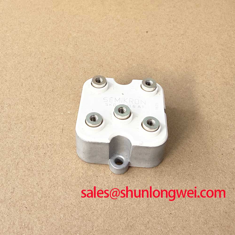
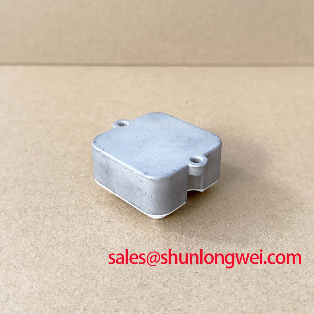
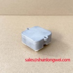
The Semikron SKD30/16A1 is a bridge rectifier module in the compact SEMIPONT 1 package. Its official electrical limits include a repetitive peak reverse voltage of 1600 V, an output current of 30 A at case temperature 85 C, a maximum forward voltage of 1.6 V, and a non-repetitive surge forward-current rating of 370 A for a 10 ms half cycle at 25 C. These ratings define the module boundary; they do not replace validation of the surrounding transformer, input protection, busbar, fuse, cooling path, and load duty cycle.
For a field replacement, remove residual thermal compound from the heatsink using a material suitable for the maintenance procedure, then inspect the contact plane under suitable lighting. Hardened compound, embedded debris, corrosion, or a bowed mounting surface can prevent even heat transfer. Apply thermal interface material as a thin, uniform film that fills microscopic surface irregularities without forming a thick insulating layer. Place the module squarely on the heatsink and tighten mounting hardware progressively in an alternating sequence so contact pressure develops evenly across the base.
Maintenance Note: Periodically monitor contact-temperature rise and verify that the cooling air path remains clear before a gradual thermal problem becomes an unplanned rectifier outage.
Mounting torque is not supplied in the provided official data for this model. Therefore, the torque value, fastener grade, washer arrangement, and tightening sequence must be taken from the original equipment documentation or the applicable Semikron mechanical documentation. This is a Design Consideration: enough clamping force is needed for stable thermal contact, while excessive or uneven force can distort the package and compromise the mechanical interface.
The stated 3000 V~ isolation voltage is an Official Datasheet Specification for the module insulation boundary. During maintenance, insulation coordination still depends on the complete assembly, including creepage paths, mounting hardware, heatsink connection, contamination level, enclosure conditions, and the test method used by the equipment manufacturer. Do not infer a complete system safety certification from the isolation-voltage rating of an individual module.
At the DC output terminals, check for busbar movement, discoloration at compression joints, and strain transferred from cables into the module terminals. A low-inductance, mechanically supported current path is a Design Consideration because changing current can generate voltage excursions in the surrounding circuit. The appropriate layout is determined by the actual transformer leakage inductance, line protection, conductor geometry, DC-link arrangement where present, and switching or commutation behavior in the complete equipment.
When evaluating rectifier-module construction and lifecycle support, the Semikron-Danfoss Power Electronics & Modules Official Hub is a useful manufacturer resource for broader power-semiconductor reference material. For this specific repair, the installed equipment schematic and the original service instructions remain the controlling references for terminals, fuses, and mounting interfaces.
Field Diagnostics & Commissioning: High-Current DC Rectifier Topologies for Green Hydrogen Systems
In a high-current green hydrogen electrolyzer DC power rectifier, the SKD30/16A1 should be evaluated as one element within a larger rectification arrangement, rather than assumed to carry the complete plant DC output. Equipment designers can use multiple bridge sections, transformer secondary windings, interphase magnetic components, or parallel current paths to meet the required output. The installed topology, not the module label alone, establishes each bridge section's current share and electrical stress.
A six-pulse bridge receives three-phase AC and produces a pulsating DC waveform. A twelve-pulse arrangement commonly uses phase-shifted transformer secondary systems and combines rectifier outputs to reduce characteristic supply-side harmonic content. In either architecture, a replacement module must match the original circuit position and terminal orientation. Confirm the marked AC and DC connections against the machine schematic before energization. Incorrect placement can create a direct fault path even when the module's voltage and current ratings appear suitable.
Interphase transformer behavior deserves practical attention where parallel bridge outputs are used. Its purpose is related to balancing current between paths that do not have perfectly identical instantaneous voltages. Unequal cable lengths, uneven secondary connections, loose bus joints, unequal thermal conditions, or altered transformer connections can affect current distribution. A bridge module that runs hotter than its neighboring location may indicate a system-level imbalance, but the observation alone does not prove the root cause. Compare voltage drop, connection integrity, thermal pattern, transformer-secondary conditions, and waveform behavior using the approved service method.
| Official Specification | SKD30/16A1 Rating | Maintenance Relevance |
|---|---|---|
| Repetitive peak reverse voltage VRRM | 1600 V | Verify against the maximum repetitive reverse stress specified for the installed rectifier circuit. |
| Output current ID | 30 A at TC = 85 C | Assess with the actual heatsink condition and current-sharing arrangement. |
| Surge forward current IFSM | 370 A at 10 ms, 25 C | Relevant to non-repetitive inrush and fault-transient assessment, not normal load operation. |
| Forward voltage VF | 1.6 V maximum | Use as the official conduction-loss boundary under the conditions defined by the source data. |
| Isolation voltage Visol | 3000 V~ | Check chassis, heatsink, and enclosure insulation practices separately. |
| Package | SEMIPONT 1 | Confirm mechanical fit, terminal access, and cooling-interface compatibility. |
No official fuse I2t value or coordination table is included in the supplied specification for this product. Fuse selection must therefore be verified from the equipment fuse documentation, prospective short-circuit current, transformer capability, conductor rating, and the protective-device data. Treating the 370 A non-repetitive surge rating as a fuse-selection value would be incorrect because a fuse clearing characteristic and semiconductor surge withstand are different measurements.
For applications requiring a higher voltage or current class, engineers can compare the original system requirements with related product information such as SKD82/18. This reference is not a replacement instruction. Electrical topology, terminal layout, thermal interface, protective coordination, and equipment approval requirements must be checked before any part-number change.
SKD30/16A1 Thermal-Electrical Optimization: Non-Repetitive Surge On-State Current Practical Tuning
The 370 A rating is the official non-repetitive surge forward-current limit for a 10 ms half cycle at 25 C. It is useful when reviewing transformer energization, capacitor charging where applicable, fault clearing, or abnormal line events, but it must not be interpreted as a continuous-current capability. The normal output-current rating remains 30 A at TC = 85 C, and actual service temperature must be assessed from the installed cooling system.
When a rectifier has been exposed to an overcurrent event, begin with a de-energized inspection. Check upstream fuses, transformer-secondary connections, output conductors, heat sink cleanliness, terminal hardware, and evidence of thermal stress. A diode-check measurement can help identify an obvious short or open condition when performed according to the equipment procedure, but meter readings are instrument-dependent and should be compared with a known-good circuit path or an approved reference unit. Measurements made while parallel paths remain connected can be misleading.
Before restoring power, verify that no damaged conductor, failed suppression component, or transformer fault remains capable of repeating the event. A replacement bridge cannot correct the underlying source of a surge. During controlled recommissioning, observe input and output behavior using the site's approved instrumentation and safety controls. Compare phase balance, output ripple, temperature distribution, and protective-device operation with the equipment baseline. Any measured reverse-voltage stress must remain within the official 1600 V VRRM rating under the actual operating conditions.
The maximum 1.6 V forward-voltage specification is relevant because rectifier conduction loss becomes heat that must pass through the module mounting interface and heatsink. The exact junction temperature, permissible load cycle, and derating behavior are system-determined because they depend on waveform, ambient conditions, airflow, heatsink design, and actual current sharing. A Design Consideration is to inspect aged thermal compound and restricted airflow during planned maintenance, particularly where the rectifier enclosure experiences dust loading, humidity, temperature cycling, or periods of low fan performance.
In high-current transformer and conductor arrangements, proximity effect can influence AC resistance and heating distribution in adjacent conductors. The physical principle is described in this reference on proximity effect in high-frequency magnetics and transformers. Its practical relevance depends on the equipment frequency, conductor arrangement, and transformer design; it should not be used to infer a specific loss value for the SKD30/16A1 installation without measurement or validated system calculations.
Transient Dynamics & Electrical Design: AC Line Surge Immunity and Lightning Transients on SKD30/16A1
The 1600 V VRRM rating defines the bridge module's repetitive peak reverse-voltage capability. It does not mean that an installation can omit coordinated AC input protection. Lightning-related events, utility switching, transformer behavior, and load disturbances are system phenomena. Surge-protection devices, line reactors, RC networks, grounding arrangements, and protective fuses must be assessed at equipment level using the original design requirements and the applicable site standard.
When investigating line-side damage, examine the entire protection chain before installing a replacement module. Inspect surge-protection components for visible distress, verify protective-device continuity where appropriate, review grounding connections, and confirm that AC terminal insulation and busbar clearances have not been compromised by heat or contamination. A failed protective component can alter the voltage presented to a bridge, while a loose connection can create localized heating and intermittent behavior. Neither condition can be confirmed from a visual check alone; measurement should follow the equipment's lockout, test, and recommissioning process.
For a complete rectifier cabinet, minimizing parasitic loop inductance is an Engineering Recommendation where changing current can create unwanted voltage overshoot. The system engineer should verify peak voltage margins against DC-link voltage, transformer conditions, wiring geometry, and measured transient waveforms. RC snubber suitability and metal-oxide-varistor selection also depend on the actual line voltage, surge environment, energy exposure, upstream impedance, coordination with other protection devices, and the service strategy of the equipment. No fixed snubber or MOV value can be assigned from the supplied module ratings alone.
Moisture control is equally important in industrial rectifier cabinets. Check enclosure seals, heater or ventilation functions where fitted, cable-gland integrity, and signs of condensation near high-voltage terminals. Clean conductive dust from insulated surfaces only with procedures compatible with the facility safety rules and component materials. Re-tighten terminals only to the documented torque requirement after confirming the conductor and hardware condition.
For maintenance teams evaluating transient behavior in industrial drive and rectifier environments, Unlocking Efficiency in Industrial Drives provides related context on disciplined power-stage measurement. The SKD30/16A1 remains a bridge rectifier module, so its suitability must be established from its own official ratings, original circuit documentation, and measured conditions in the intended equipment.