
Content last revised on October 15, 2026
Transient Dynamics and Electrical Design for Braking Applications
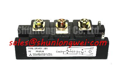
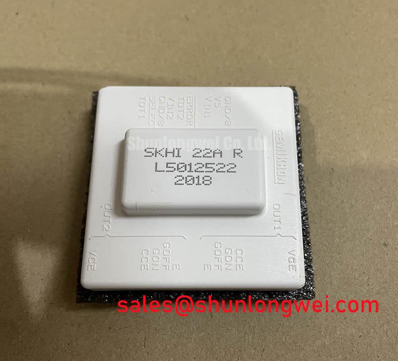
The SKHI-22AR is a Semikron IGBT gate-driver unit, not the power IGBT module itself. With the DC link isolated and fully discharged, check the driver marking, connector identity, and associated power-module terminals before connecting a gate-drive harness. The 1700 V and 20 A values must be verified against the specific IGBT module used in the equipment; they should not be attributed to the SKHI-22AR without applicable manufacturer documentation. Switching performance, internal topology, isolation ratings, and protection limits must be matched to the equipment documentation.
For incoming inspection, use an ESD-controlled bench and compare the measured connector and signal behavior with a known-good reference from the same equipment family. A diode-test reading may help identify an unexpected open or short condition in accessible power paths, but the reading itself is not a substitute for the manufacturer’s complete electrical test procedure. Do not apply gate-drive or DC-link voltage during a basic cold inspection.
A braking circuit places the associated IGBT module and driver in a demanding energy-transfer role: motor deceleration raises the DC-link energy, while the braking switch and ballast resistor convert that energy into heat. When evaluating an SKHI-22AR in a high-dynamics multi-axis CNC or robotics servo, start with the actual deceleration profile, DC-link operating range, braking duty cycle, the selected power module, and resistor thermal capacity rather than treating any unverified 1700 V or 20 A values as a complete system design limit.
Design Consideration: the braking IGBT, gate driver, and resistor should be assessed together because the semiconductor controls current while the resistor absorbs the resulting pulse energy. The system engineer should verify the resistor’s pulse-energy curve, repetition capability, thermal recovery, and enclosure heat path against the machine’s worst credible stopping sequence. A short emergency stop and repeated servo deceleration can impose very different thermal conditions.
Keep the high-current commutation loop compact and physically separated from sensitive gate and feedback wiring. This reduces the effect of stray inductance on turn-off overshoot and helps prevent switching noise from coupling into encoder, resolver, or controller circuits. The exact clearance arrangement depends on the bus voltage, insulation system, pollution environment, enclosure design, and applicable safety requirements. Verify peak voltage at the switching terminals with a suitably rated differential probe during controlled commissioning.
When a servo drive reports intermittent DC-link overvoltage during deceleration, inspect the braking command timing, resistor connections, contactor condition, driver behavior, and voltage waveform as a group. A delayed braking command, excessive wiring inductance, resistor thermal limiting, or gate-drive disturbance may produce similar symptoms. The investigation should compare the command signal, driver output and gate-emitter waveform, DC-link voltage, and braking current under the same motion profile.
For thermal-cycling assessment, record the case temperature trend of the associated power module during repeated acceleration and braking events and compare it with the module’s applicable thermal data. The Semikron-Danfoss Power Electronics & Modules Official Hub provides manufacturer-level technology context at Semikron-Danfoss Power Electronics & Modules. Package attachment, heatsink flatness, thermal interface condition, and airflow all influence the real temperature swing seen by the assembly.
Gate-Drive Isolation, Terminal Verification, and Practical Tuning
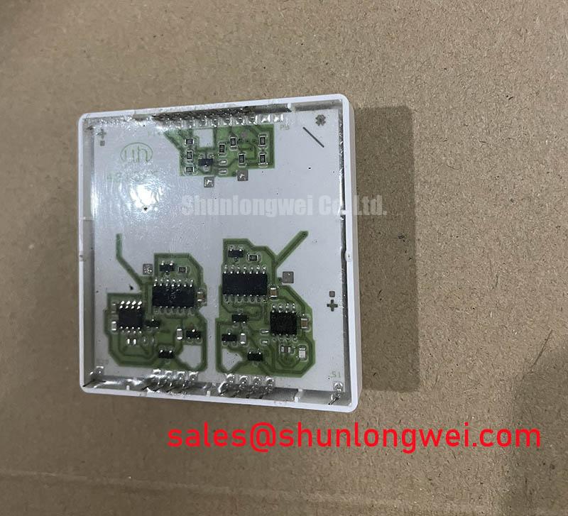
Gate-drive isolation must be treated as a complete signal path rather than a single voltage rating. Incoming inspection should first confirm the physical connector and terminal identity against the original equipment drawing, then check that the gate-emitter control circuit is not exposed to an unintended power-terminal potential. The SKHI-22AR is the driver in this arrangement; its applicable supply, isolation, output-current, and protection specifications must be taken from the relevant driver documentation and the complete assembly documentation.
If the equipment design requires an isolation barrier above 5 kV or a common-mode transient immunity above 100 kV/µs, treat those figures as system requirements and verify them against the applicable Semikron documentation and the complete driver assembly. They should not be assumed from the voltage rating of the associated IGBT module or from the driver name. The isolation barrier includes the driver, PCB spacing, connector system, mechanical supports, contamination control, and the measurement arrangement used during validation.
Check creepage and clearance along the real current path, including terminal hardware, busbars, washers, cable lugs, PCB edges, and nearby grounded metalwork. Surface contamination can reduce practical insulation performance even when the nominal layout appears adequate. For a repair, reproduce the original routing and support points before changing cable length or adding an adapter board.
Gate-loop wiring should be short, mechanically secure, and kept away from the power commutation loop where the machine layout permits. Designers should tune turn-on and turn-off behavior from measured gate-emitter waveforms, collector-emitter overshoot, switching loss, and electromagnetic interference results. A suggested gate resistor value is a bench-tuning starting point only; the final value is determined by the driver output capability, gate charge, switching frequency, thermal result, and system waveform.
In applications that include a freewheel diode, reverse-recovery behavior can influence both voltage overshoot and radiated noise. The diode’s reverse-recovery softness factor, junction temperature, commutation loop geometry, and DC-link impedance should be evaluated together. No diode dynamic parameter should be assigned to the SKHI-22AR without the corresponding device and circuit documentation.
Bench Tip: keep the driver and associated power module in an ESD-controlled area, discharge the DC link, and record cold diode-test readings and terminal-to-case insulation observations before applying any gate signal.
Mechanical fastening also affects electrical stability. Busbars should be supported so that vibration does not transfer continuous bending force into the power terminals. Use the equipment manufacturer’s specified hardware and torque procedure; do not infer a module-specific tightening torque from the Semitrans package name or from the SKHI-22AR driver. After assembly, inspect for tilted lugs, trapped washers, damaged insulation films, and unintended contact between the busbar and heatsink.
| Evaluation point | SKHI-22AR | Replacement comparison reference |
|---|---|---|
| Device type | Semikron IGBT gate-driver unit | Compare the applicable driver documentation |
| Voltage and current ratings | Do not attribute the associated IGBT module’s ratings to the SKHI-22AR | Verify the candidate driver and power module ratings independently |
| Associated package | Confirm the power module and mechanical assembly separately | Confirm mechanical outline and terminal compatibility |
| Cross-reference review | Original equipment pinout and gate-drive conditions apply | FZ1200R17HE4 comparison reference |
This comparison is a screening aid, not a blanket replacement recommendation. A candidate driver and power module must match electrical ratings, switching behavior, package geometry, terminal arrangement, thermal interface, gate-drive requirements, and protection coordination. The equipment engineer should also review the wider Industrial Applications reference when assessing a high-energy drive environment.
Circuit Protection and Short-Circuit Energy Coordination
Protection coordination begins with the relationship between the semiconductor fuse, DC-link source impedance, gate-driver shutdown response, and the selected power module’s permitted short-circuit stress. The SKHI-22AR is a gate-driver unit; it does not by itself define the voltage or current rating, fuse choice, short-circuit withstand duration, or total clearing requirement of the associated IGBT module.
Select a high-speed semiconductor fuse by comparing its published total-clearing I²t, prospective fault current, voltage capability, interrupt rating, and installation arrangement with the drive’s measured or calculated fault envelope. The fuse, power module, and driver must be evaluated as a coordinated protection system. Cable inductance, DC-link capacitor placement, busbar construction, and contact resistance can materially change the energy delivered before interruption.
Place the protection device so that an internal fault does not force the full DC-link energy through unnecessary bus length or loosely supported joints. Inspect fuse clips, laminated busbars, terminal surfaces, and pressure points during service work. A damaged connection may create local heating and voltage disturbance without presenting as a simple semiconductor failure during a cold bench test.
For a suspected short-circuit event, document the gate-emitter resistance condition, accessible diode paths, fuse condition, busbar marks, DC-link capacitor status, and driver fault history before installing another module. Compare the measured signal path with a known-good channel where available. A replacement module should not be energized until the original trigger, clamp, current-sensing, and shutdown circuits have been checked for a continuing fault.
High-altitude operation, cosmic-ray effects, single-event burnout, FIT values, service life, EMC compliance, and insulation reliability require application-specific evidence. Do not assign a numerical SEB rate, lifetime prediction, or EMC certification to the SKHI-22AR or the associated power module without an authoritative test report or applicable manufacturer documentation. For thermal packaging background, consult Semikron Sintering Technology, while keeping material-process information separate from confirmed product parameters.
Before returning a repaired CNC or robotics servo axis to service, verify the gate signal under controlled low-energy conditions, confirm the DC-link charging sequence, observe braking behavior, and review the protection trip response. The final acceptance test should use the machine manufacturer’s operating limits and the recorded electrical waveform evidence for that specific drive assembly.