Content last revised on December 2, 2025
SKiiP83AC12iS T2: High-Reliability 1200V IPM for Demanding Industrial Drives
Introduction to a Robust Power Conversion Solution
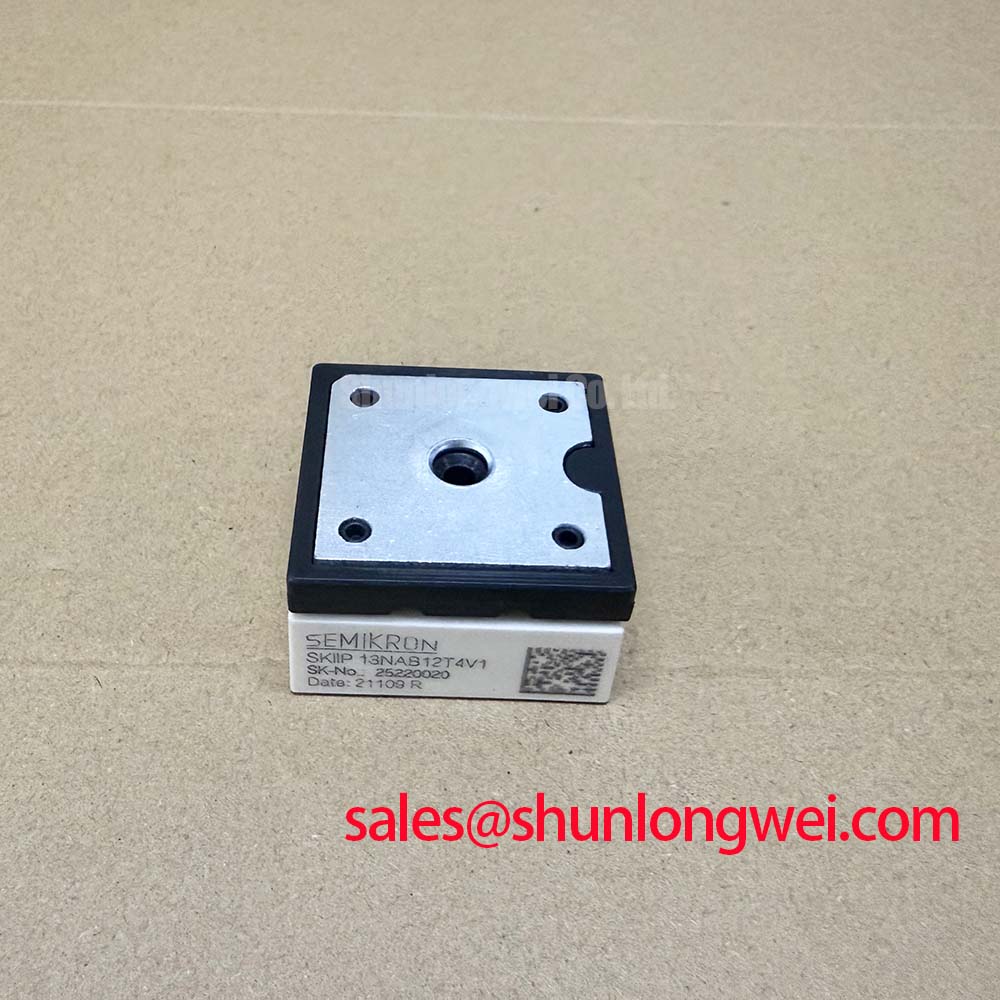
The SKiiP83AC12iS T2 is an advanced Intelligent Power Module (IPM) engineered by Semikron for high-performance power conversion systems. This module integrates a three-phase IGBT inverter bridge into a compact, reliable package, delivering key specifications of 1200V and a nominal current of 125A at a 25°C heatsink temperature. Key engineering benefits include exceptional operational reliability due to solder-free pressure contact technology and simplified thermal management enabled by its low thermal resistance. It directly addresses the need for robust power stages in industrial environments where thermal cycling and mechanical vibration are significant challenges. What is the key advantage of its integrated design? It combines power stages with intelligent drivers, enhancing system protection and simplifying the overall design process.
Key Parameter Overview
Decoding Specifications for System Reliability and Performance
The technical specifications of the SKiiP83AC12iS T2 are tailored for robust performance in high-power inverter applications. The parameters outlined below are critical for system design, thermal modeling, and ensuring long-term operational reliability.
| Parameter | Conditions | Value |
|---|---|---|
| Inverter IGBT Ratings | ||
| Collector-Emitter Voltage (VCES) | - | 1200 V |
| Continuous Collector Current (IC) | Theatsink = 25°C / 80°C | 125 A / 85 A |
| Peak Collector Current (ICM) | tp < 1 ms | 250 A (at Theatsink=25°C) |
| Collector-Emitter Saturation Voltage (VCEsat) | IC = 100 A, Tj = 125°C | Typ. 3.1 V, Max. 3.7 V |
| Inverse Diode Ratings | ||
| Forward Current (IF) | Theatsink = 25°C / 80°C | 80 A / 53 A |
| Peak Forward Current (IFM) | tp < 1 ms | 160 A (at Theatsink=25°C) |
| Forward Voltage (VF) | IF = 75 A, Tj = 125°C | Typ. 1.8 V, Max. 2.3 V |
| Thermal and Mechanical Ratings | ||
| Operating Junction Temperature (Tj) | - | -40 to +150 °C |
| Thermal Resistance, Junction-to-Heatsink (Rth(j-h)) | Per IGBT | Max. 0.25 K/W |
| Isolation Voltage (Visol) | AC, 1 minute | 2500 V |
For detailed specifications and performance curves, please refer to the official component documentation. Download the SKiiP83AC12iS T2 datasheet for detailed specifications and performance curves.
Application Scenarios & Value
Delivering Uncompromising Reliability in Industrial Motor Control
The SKiiP83AC12iS T2 is engineered for applications where operational uptime and resilience to harsh conditions are non-negotiable. Its primary value is demonstrated in high-power Variable Frequency Drives (VFDs) used to control large industrial motors in sectors such as manufacturing, material handling, and HVAC systems. In these environments, a common engineering challenge is thermal fatigue failure caused by frequent start/stop cycles and load variations. The module's pressure contact technology directly mitigates this risk by eliminating solder layers, a primary point of failure in conventional modules. This results in superior power cycling capability and an extended operational lifespan.
This module's low VCEsat of 3.1V (typical at 125°C) directly translates to lower conduction losses during operation. For a system designer, this means less waste heat is generated for a given current, simplifying the thermal management system. This can lead to smaller, more cost-effective heatsinks and a more compact overall inverter design. The integrated gate driver and protection features further streamline the design process, reducing component count and improving system-level reliability by ensuring the IGBTs operate within their Safe Operating Area (SOA). For applications requiring different current levels but similar integrated functionality, the SKiiP39GA12T4V1 can be considered as part of a scalable design strategy.
Frequently Asked Questions (FAQ)
How does the pressure contact technology in the SKiiP83AC12iS T2 enhance reliability compared to standard soldered modules?
Pressure contact technology creates a direct, solder-free connection between the DBC substrate and the heatsink. This design eliminates solder fatigue, which is a common failure mechanism in power modules subjected to frequent temperature changes (thermal cycling). The result is a significantly longer operational lifetime and higher resilience to mechanical shock and vibration.
What is the significance of the Rth(j-h) value of 0.25 K/W for system design?
The thermal resistance from junction-to-heatsink (Rth(j-h)) quantifies how efficiently heat can be transferred from the active semiconductor chip to the cooling system. A low value like 0.25 K/W indicates very efficient heat dissipation. For engineers, this means the IGBTs will run cooler under load, allowing for higher power density, improved system reliability, or the use of a smaller, more cost-effective heatsink.
Can the SKiiP83AC12iS T2 be used in parallel to achieve higher output currents?
While paralleling IGBT modules is a common technique to increase current capacity, it requires careful design considerations to ensure balanced current sharing. Factors like gate drive symmetry, busbar layout, and thermal uniformity are critical. For specific guidance on paralleling SKiiP modules, consulting the manufacturer's application notes on IGBT Paralleling is essential to ensure a reliable and safe implementation.