Content last revised on September 15, 2026
Before connecting the replacement, isolate the power stage, protect the work area against ESD, and record the module markings and terminal arrangement against the original equipment documentation. For SKKH250/12E, the incoming inspection should then verify the rated electrical boundary, inspect the housing and baseplate for mechanical damage, and compare cold-state terminal behavior with a known-good reference.
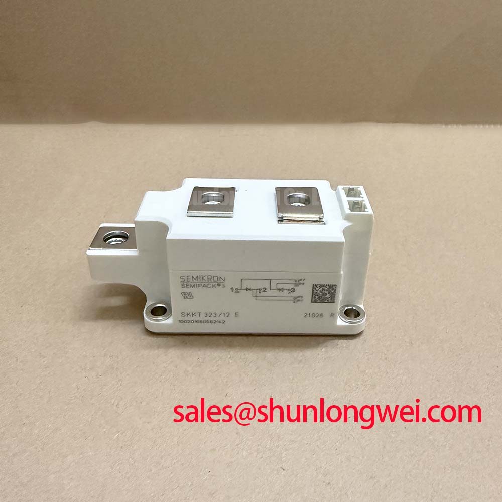
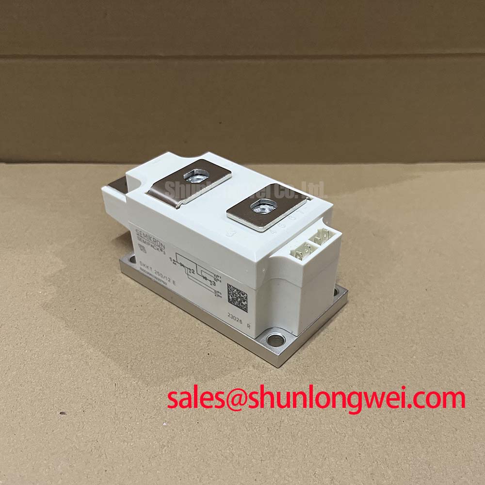
The Semikron SKKH250/12E is a high-current dual-thyristor module intended for controlled power conversion where repetitive line voltage, surge coordination, thermal transfer, and isolation must be reviewed together. Its published ratings make it a candidate for evaluation in medium-frequency induction melting and metal hardening power supplies, subject to the converter topology, firing circuit, cooling assembly, and protection network used by the equipment manufacturer.
| Parameter | Official Specification | Engineering Significance |
|---|---|---|
| V(RRM) | 1200 V | Maximum repetitive peak reverse voltage specified for the device |
| I(TAV) | 250 A at Tc = 85°C | Average on-state current rating under the stated case-temperature condition |
| I(TSM) | 9000 A | Maximum peak non-repetitive surge current for a 10 ms half-sinusoidal pulse |
| i2t | 405,000 A2s | Reference value for fuse coordination and short-circuit protection review |
| Rth(j-c) | 0.11 K/W | Specified thermal resistance from junction to case |
| Visol | 3000 V AC | Specified isolation voltage for the module construction |
These figures are official specification values supplied for this product page. They do not, by themselves, establish the permissible current in every operating cycle, the complete surge capability of an assembled converter, or compliance of the finished furnace with an EMC or safety standard. The system designer must check the complete datasheet conditions and the actual electrical waveform.
Assembly Integrity & Layout Architecture: Implementing AC Input Transient Overvoltage Clamping for SKKH250/12E
Start the installation review at the AC input path and follow the conductors toward the thyristor junctions. The 1200 V V(RRM) rating is a repetitive reverse-voltage boundary, not a substitute for line transient suppression. Induction furnace supplies can contain commutation disturbances, transformer leakage effects, and switching events that must be measured at the module terminals. An AC surge study may refer to the test philosophy of IEC 61000-4-5, but the module itself should not be described as independently compliant with that system-level standard.
A Design Consideration is to place the surge-limiting and damping network so that its connection inductance does not move the protected node away from the actual thyristor terminals during a fast event. MOV selection should be based on the system’s continuous RMS voltage, temporary overvoltage exposure, expected surge energy, and the clamping level permitted by the complete semiconductor stack. The selected MOV must also be coordinated with the upstream fuse and enclosure fault-energy limits. The SKKH250/12E rating table does not provide a universal MOV part number.
RC snubber placement deserves the same physical attention. A long branch between the snubber and the module can reduce its effectiveness against local voltage transients. The resistor and capacitor should be selected from measured commutation behavior, repetitive voltage, pulse energy, capacitor impulse capability, and the switching frequency of the equipment. This is an Engineering Recommendation rather than an SKKH250/12E factory setting. The final network should be validated with a suitably rated differential probe and an oscilloscope during controlled energization.
During terminal assembly, use the terminal names and polarity marks printed on the device and compare them with the original circuit drawing. Do not infer anode, cathode, gate, or auxiliary-terminal identity from physical position alone. The supplied product data does not state a universal terminal layout or mounting torque, so the Semikron mechanical documentation for the exact package revision must govern the fastening procedure.
Clearance and creepage should be checked after the module, busbars, insulating barriers, cable lugs, and snubber wiring are installed. The 3000 V AC Visol value is an official module isolation specification; it is not a complete insulation rating for a contaminated furnace cabinet. Designers should verify pollution environment, material group, working voltage, altitude effects, enclosure spacing, and the test method required by the finished equipment standard.
SKKH250/12E Circuit Protection & Reliability: Calibrating Saturable Reactor and Snubber Sizing to Protection Requirements
The 405,000 A2s i2t value is useful when reviewing semiconductor fuse coordination, but it should be read together with the fuse manufacturer’s pre-arcing and clearing characteristics. A fuse with a nominal current that appears suitable may still fail to protect the module if its let-through energy, prospective fault current, clearing time, or installation inductance is unsuitable. The actual coordination must be checked against the fuse curve and the fault level of the induction-heating supply.
The 9000 A I(TSM) value applies to the specified non-repetitive 10 ms half-sinusoidal surge condition. It should not be treated as a repeatable operating allowance or as permission to omit semiconductor fusing. Record the prospective short-circuit current, waveform duration, line impedance, and number of applied events when evaluating a protection scheme. If the equipment includes a series saturable reactor, its effect on current rise, commutation overlap, fault limitation, and thermal recovery should be confirmed through waveform testing.
A Design Consideration for the saturable reactor is to evaluate the complete magnetic component rather than selecting it from current alone. Core reset, volt-second balance, saturation timing, winding temperature, and the effect of load changes can alter the current presented to the thyristor module. The reactor and fuse must be assessed as one protection system, while the snubber must be checked for both normal switching losses and abnormal transient energy.
For incoming inspection, use a suitable low-voltage semiconductor test only when the module is fully disconnected and the terminal configuration is known from the relevant documentation. Compare the terminal-response indications with a retained known-good reference under the same test leads and ambient conditions. A meter reading is a screening observation, not proof of blocking performance, surge capability, or gate integrity. Abnormal results should be followed by controlled insulation and semiconductor tests using equipment appropriate to the manufacturer’s limits.
For technical background on voltage stress and switching behavior in related high-voltage power conversion systems, engineers may consult The 1200 V CoolSiC™ MOSFET Advantage in Three. The article concerns a different semiconductor technology and should be used as system-level reference material, not as a substitute for the SKKH250/12E data.
Preventing Spurious Faults: Gate Trigger Current Dynamics Guidelines for SKKH250/12E
The firing circuit should be inspected as part of the module replacement rather than treated as an unrelated control-board issue. Confirm the gate and cathode references from the original schematic, check the pulse transformer or optocoupler path, and observe the gate-to-cathode waveform at the module under operating conditions. A clean signal at the driver output does not guarantee the same signal at the power-terminal location because common-mode movement and wiring inductance can affect the local reference.
Specific gate trigger current, gate pulse rise-time, latching-current, holding-current, and gate power limits were not included in the supplied official parameter set. They should therefore be taken from the applicable Semikron datasheet revision rather than estimated from another module. A proposed firing approach using fast current rise, a back-porch pulse, or multiple pulses is an Engineering Recommendation only when confirmed against the device’s published gate characteristics and the converter’s control timing.
Designers should keep the gate-drive return physically close to its corresponding cathode reference and separate it from high-current commutation paths. A Kelvin emitter connection should not be assumed for this thyristor module; use only the terminals explicitly identified by the manufacturer. The gate circuit should also be evaluated for common-mode ground bounce, unintended dv/dt coupling, pulse-transformer reset, and control-board isolation. If a negative turn-off bias is considered, its voltage, duration, and current must be verified from the exact gate-drive and device documentation rather than copied from an IGBT application.
When a firing fault is reported, capture the gate-to-cathode waveform and the main-terminal voltage at the same time. Check whether the trigger pulse reaches the module, whether the reference moves during commutation, and whether the fault repeats at a particular load or line phase. This method avoids assigning a single cause to an intermittent trigger event. The result should be compared with the known-good signal path and the applicable factory gate limits.
Semikron’s published information on Semikron SEMIPACK® Thyristor / Diode Modules provides useful product-family context. Device-family information should not replace the exact SKKH250/12E electrical and mechanical documentation. Related semiconductor construction information is also available through Semikron CAL Diode Technology, although it does not establish an SKKH250/12E internal construction claim.
💡 Bench Tip: Keep the module and the comparison unit at the same cold ambient condition, use ESD protection, and disconnect all external gate and power wiring before recording static measurements.
Benchtop Waveform Tuning: Mitigating Stress via Baseplate Thermal Resistance on SKKH250/12E
The official Rth(j-c) of 0.11 K/W describes the specified junction-to-case thermal path. It does not describe the complete junction-to-ambient result after the baseplate, thermal interface, heatsink, airflow, and cabinet temperature are included. For a medium-frequency induction melting or hardening furnace, the cooling assembly should therefore be evaluated under the actual duty cycle rather than by relying on the module rating alone.
Inspect the baseplate and heatsink contact surfaces for burrs, contamination, bowing, or trapped debris. Apply the thermal interface material according to the interface-material supplier’s installation instructions and use the mechanical fastening sequence specified for the exact Semikron package. Since a verified mounting-torque value was not included in the supplied product data, do not adopt a generic torque figure as an SKKH250/12E factory requirement. Excessive or uneven fastening force can distort the assembly; insufficient force can increase thermal interface resistance.
Measure temperature at the case reference point defined by the applicable documentation and correlate it with electrical waveform data. Observe the relationship between load current, firing angle, commutation behavior, case temperature, and cooling-fluid or heatsink conditions. The 250 A I(TAV) rating at Tc = 85°C is conditional and should not be converted directly into an unrestricted RMS current for an induction-heating converter. Designers should verify conduction losses, overload duration, thermal cycling, and the permitted operating point using the full manufacturer data.
During bench waveform tuning, minimize the high-current loop area and keep measurement leads away from the gate reference. Verify peak terminal voltage, current rise, commutation overlap, and transient ringing at the module terminals. If the waveform changes after tightening, replacing the interface material, or rerouting the gate lead, investigate mechanical contact and parasitic coupling before changing the firing circuit. Any protection adjustment should be retested at the intended line condition and load range.
For a cross-reference review, engineers may examine the objectively described SKKT 250/14E as a related Semikron thyristor/diode module listing. It should not be treated as an automatic substitute. Voltage class, current conditions, circuit topology, terminal arrangement, thermal interface, isolation requirements, and control characteristics must all be matched by the system engineer before considering any alternate device.