Content last revised on September 19, 2026
SKKH92/18E Thermal-Electrical Optimization: Type-2 Coordination: Sub-Cycle Dead-Short Practical Tuning
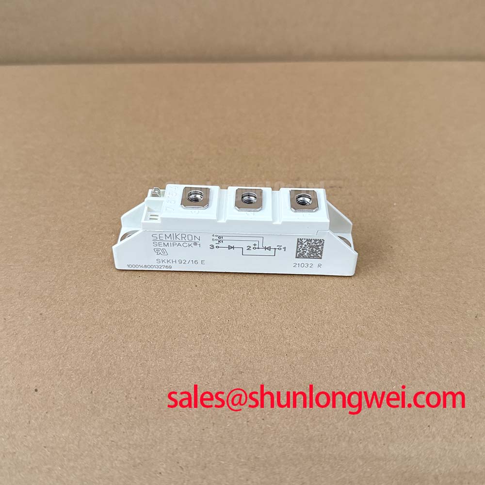
With the converter isolated and discharged, first verify that the installed unit’s nameplate matches SKKH92/18E, then inspect the Semipack housing, power terminals, gate connections, heatsink contact face, and surrounding busbar hardware for signs of heat exposure, contamination, looseness, or condensation. This is a Semikron thyristor and diode module specified at 1800 V and 92 A in a Semipack housing, and those official ratings should be checked against the original equipment documentation before a maintenance replacement or converter repair is approved.
For medium frequency induction melting and metal hardening furnace power supplies, this device should be assessed as part of its complete rectifier or controlled-power topology. The module itself does not establish furnace output power, firing angle, commutation margin, harmonic content, cooling capacity, or protective coordination. Those conditions depend on the mains arrangement, transformer, choke, fuse system, gate controller, busbar geometry, and load characteristics. The system integrator should therefore confirm the original circuit position and terminal allocation before reconnecting any power or control wiring.
| Item | Declared Value | Classification |
|---|---|---|
| Product model | SKKH92/18E | Official product identification |
| Manufacturer | Semikron | Official product identification |
| Rated voltage | 1800 V | Official specification |
| Rated current | 92 A | Official specification |
| Housing | Semipack | Official package specification |
| Product class | Thyristor and diode module | Product classification |
A dead short in a controlled rectifier can develop faster than a maintenance team can observe from cabinet indicators. Before fitting an SKKH92/18E, trace the power path from the incoming supply through the protective fuse, contactor, transformer or reactor, controlled rectifier bridge, DC link, and furnace inverter section. The purpose is to establish whether the fuse has been selected and coordinated for the installed semiconductor branch rather than merely for the cabinet feeder.
Type 2 coordination is a system-level protection objective, not an official capability claim for this module. In practical terms, it asks whether the selected semiconductor fuse can interrupt fault energy quickly enough that adjacent contactors, conductors, and power-semiconductor assemblies avoid unacceptable damage after a short-circuit event. The fuse manufacturer’s coordination documentation and the original converter schematic are the controlling references. Fuse pre-arcing and total clearing I²t information must be compared with the applicable surge-current and I²t withstand information in the exact module datasheet revision. Those values are not established by the 1800 V and 92 A ratings alone.
For a furnace rectifier, the firing controller must also be considered. A loss of pulse synchronization, a failed isolation interface, or unwanted gate pulses can cause abnormal current paths that a normal operating current measurement does not reveal. Maintenance personnel should verify that gate leads return to their intended terminals, that trigger transformers or isolated driver channels are connected as documented, and that no control lead is trapped beneath busbars or heatsink hardware.
Phase-controlled input stages are often examined for conduction-angle stability because firing-angle changes affect input current waveform and higher-order mains harmonics. This is a Design Consideration rather than a module-specific performance guarantee. The appropriate harmonic mitigation method is determined by the complete installation, including source impedance, transformer arrangement, line reactor selection, filter equipment, and utility requirements. Do not infer compliance with any system-level EMC or power-quality standard from the presence of this semiconductor module.
Where an equipment bill of materials calls for an alternative Semikron position, engineers can compare documented circuit function, voltage class, current requirements, terminal arrangement, and mounting interface with the SKKH273/18E. This is a neutral reference for cross-checking an installed design; it is not a declaration that the two products are interchangeable. The original circuit documentation, protective coordination study, and mechanical drawing remain decisive.
⚠️ Maintenance Note: After any fuse operation or terminal service, recheck power-joint tightness and monitor contact temperature rise during controlled recommissioning while confirming that cooling-air passages remain clear.
Transient Dynamics & Electrical Design: Junction-to-Heatsink Heat Dissipation in SKKH92/18E
The thermal inspection starts at the mounting face, not at the cabinet fan. Remove old interface material only when the assembly is safely isolated, then examine the heatsink surface for corrosion, burrs, embedded debris, flatness concerns, and evidence that the former module was seated unevenly. A clean, continuous thermal interface supports heat transfer from the semiconductor mounting base into the heatsink. Uneven clamp loading can leave local dry areas or mechanically stress the housing, neither of which should be accepted as a normal installation condition.
The thermal resistance from junction to case and the permitted case or junction operating conditions must be taken from the specific official datasheet for the installed device. They are not provided by the declared product identity, current rating, voltage rating, or Semipack designation. A maintenance record should distinguish official semiconductor thermal data from the heatsink performance measured or specified for the machine. Fan condition, filter blockage, duct leakage, ambient temperature, and recirculated hot air all influence the thermal result seen in service.
Use the original equipment manufacturer’s mounting pattern, screw grade, tightening sequence, and torque requirement. If the original requirement is unavailable, a qualified system engineer should obtain the applicable mechanical documentation rather than applying a generic torque figure to the Semipack housing. Power-terminal tightening should likewise follow the terminal and hardware documentation. Excessive force can damage threads or distort an assembly, while insufficient force can increase contact resistance and produce local heating.
In induction furnace supplies, thermal demand can change materially with batch cycle, melt profile, hardening duty, cooling-water state, and commanded output. A module that appears stable during a short unloaded test may experience a different temperature trajectory during a full production sequence. Engineering Recommendation: trend heatsink temperature, cabinet inlet and outlet conditions, and terminal-area temperature through the actual duty cycle, then compare the results with the equipment’s approved thermal limits.
Regenerative braking choppers and braking resistors are sometimes present in industrial drive systems, but they are not established functions of the SKKH92/18E itself. When such circuits share a DC-link environment with a controlled rectifier, the service team should review the schematic to identify energy paths during deceleration, supply interruption, and fault shutdown. The resistor’s energy capability, control logic, and chopper semiconductor selection are system-determined matters.
The product family context for Semipack thyristor and diode assemblies can be reviewed through Semikron SEMIPACK® Thyristor / Diode Modules. The installation decision for this exact part should still be based on the machine’s original electrical and thermal documentation.
SKKH92/18E Thermal-Electrical Optimization: High-Frequency Switching Loss Dissipation Practical Tuning
Before attributing electrical noise or excess heat to the module, identify the switching mechanism actually used by the equipment. A thyristor-controlled stage and a fast transistor inverter stage have different commutation behavior, measurement methods, and control limitations. The designation SKKH92/18E identifies a thyristor and diode module; it should not be described as an IGBT module, and no IGBT-specific gate-drive assumptions should be transferred into its service procedure.
Diode reverse-recovery peak current and recovery time are relevant to commutation loss and transient behavior only when the applicable circuit and official device data support that assessment. No numerical Irrm or trr value should be assumed from the module’s nominal 1800 V or 92 A ratings. When investigating a commutation concern, use a suitably rated oscilloscope arrangement and compare voltage and current waveforms with a known-good operating channel or approved commissioning trace. Ringing, unexpected peak current, or irregular recovery behavior can have several causes, including layout inductance, snubber condition, firing timing, measurement setup, or a fault elsewhere in the topology.
Design Consideration: minimize the physical loop area of the commutation path to reduce inductive overshoot during changing current conditions. The required busbar arrangement, snubber network, capacitor placement, and acceptable peak margin must be verified by the system engineer during switching tests against the actual DC-link voltage and operating load. Long motor cables can create reflected voltage-wave effects in inverter-fed systems, but that is an installation-level issue to be evaluated at the motor-drive interface; it is not an inherent characteristic or specified application of this module.
For parallel semiconductor branches, static and dynamic current sharing depends on matched electrical characteristics, thermal conditions, layout symmetry, triggering consistency, and the original converter design. Positive temperature coefficient behavior in some power devices does not establish safe sharing for every topology or operating point. Do not parallel modules or alter busbar paths as a field expedient without an approved design review and measured current-sharing evidence.
Where the wider equipment investigation includes modern drive-stage efficiency topics, the technical discussion in Unlocking Efficiency in Industrial Drives provides useful context for separate IGBT-based drive technology. It does not change the topology, ratings, or firing requirements of the thyristor and diode module evaluated here.
Field Diagnostics & Commissioning: High-di/dt Gate Firing: Pulse-Train Timing in SKKH92/18E Topologies
Begin gate-circuit diagnosis with the cabinet isolated. Confirm terminal labels against the original schematic, inspect gate and reference wiring for damaged insulation or strain, and verify the condition of pulse transformers, isolated driver boards, connector retention, and control-board supply rails. A controlled rectifier depends on correct firing sequence, phase reference, pulse width, pulse amplitude, repetition strategy, and return-path integrity. These conditions are defined by the equipment design, not by the basic voltage and current ratings printed for the module.
High gate-current rise rate, holding-current behavior, and multipulse firing schemes are legitimate topics for the exact thyristor datasheet and the original firing-controller specification. The requested threshold for gate-current rise rate and any back-porch pulse arrangement should not be imposed without those documents. Engineering Recommendation: capture gate-to-reference waveforms and relevant anode-cathode behavior with the approved test method, then compare timing relationships across phases or channels under controlled low-risk conditions. This approach helps isolate a driver or synchronization issue without presenting a single measured symptom as proof of one root cause.
In medium-frequency induction melting and hardening equipment, startup and load transitions can alter the electrical environment seen by the input rectifier. The commissioning plan should verify interlocks, cooling flow indication, protective fuse status, phase sequence where applicable, control synchronization, and the absence of unintended firing before production power is enabled. If current asymmetry or unstable output is observed, review the complete signal path from reference sensing to gate pulse delivery alongside the power circuit, rather than replacing semiconductor hardware based solely on a cabinet fault code.
A related upstream rectifier or power-stage position may be documented separately in the machine design. The SKKH330/08E can be reviewed as a linked product reference when checking component records, but its application compatibility, protection requirements, and interchangeability must be verified independently. Preserve records of module position, fuse reference, heatsink condition, terminal service, waveform observations, and commissioning outcome so later maintenance decisions are based on traceable equipment history.