Content last revised on October 6, 2026
SKKT72-18E Incoming Inspection and Key Ratings
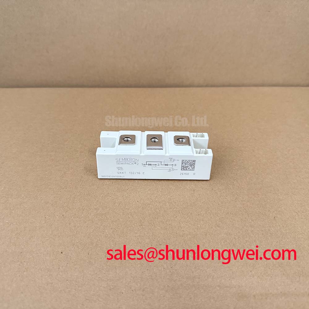
Start the incoming inspection by confirming the Semikron marking, checking the Semipack housing for mechanical damage, and recording the module’s cold terminal readings before it is connected to a firing circuit. The SKKT72-18E is a 1,800 V, 72 A thyristor module in a Semipack package. Its ratings and their specified conditions should be checked against the applicable manufacturer datasheet and original equipment documentation before replacement.
| Parameter | SKKT72-18E specification | Engineering use |
|---|---|---|
| Manufacturer | Semikron | Confirm the marking and equipment bill of materials |
| Product category | Thyristor module | Evaluate for controlled power conversion and SVC switching stages |
| Voltage class | 1,800 V | Compare with the circuit’s applied and transient voltage conditions |
| Current class | 72 A | Check current waveform, cooling conditions, and protection coordination |
| Package | Semipack | Verify terminal layout, mounting arrangement, and heatsink compatibility |
The rating values identify the device class, but they do not by themselves establish suitability for every circuit position. A grid tied static Var compensator or thyristor switched capacitor assembly can expose a power module to repetitive line current, capacitor inrush, commutation stress, and transient voltage that must be checked at system level. The engineer should compare the original circuit topology, gate firing arrangement, fuse coordination, heatsink construction, and terminal connections before authorizing a replacement.
SKKT72 18E Operational Boundaries: Evaluating Gate Trigger Current and Temperature Limits
For an incoming bench check, first isolate the module from the gate driver and discharge all connected capacitors. Identify the power terminals and gate related terminals from the Semikron documentation for the exact device revision rather than relying on a generic Semipack drawing. A resistance comparison between corresponding terminals can reveal an open connection, an unexpected short, or a mismatch between sections, but a multimeter result is only a screening observation. It is not a substitute for a controlled thyristor trigger test.
The requested gate firing conditions, including pulse rise behavior, gate current, holding current, and temperature dependence, require the official electrical characteristics for the exact SKKT72 18E datasheet revision. The voltage and current classes do not provide numerical limits for gate trigger current, gate pulse rise time, latching current, or holding current. These values should not be inferred from the 1,800 V and 72 A ratings.
As a Design Consideration, the firing circuit should deliver a repeatable gate pulse with controlled wiring inductance and a clearly defined return path. During commissioning, the engineer can observe the gate waveform and the main terminal current at reduced energy, then compare firing consistency across the expected operating temperature range. If the pulse is present but the main current does not establish as expected, inspect gate polarity, return wiring, driver isolation, load conditions, and the opposing power path instead of assigning a single cause to the module.
The same discipline applies to multi pulse firing. A pulse train may be considered by the system designer when the application requires reliable triggering under electrical noise or variable line conditions, but pulse width, repetition, and gate current must come from the device data and the firing circuit design. The module rating is not evidence that a particular firing scheme is approved.
Fuse I²t coordination is also part of the acceptance review. The correct fuse class, clearing characteristic, and permitted I²t value must be taken from the official coordination table for the relevant circuit. A replacement fuse should not be selected from the 72 A current class alone. The engineer should compare prospective fault current, fuse clearing time, semiconductor protection requirements, and the thermal path under both normal and fault conditions.
💡 Bench Tip: Use ESD protection and compare cold terminal measurements with a known good reference before applying any gate or power pulse.
Assembly Integrity and Layout Architecture: Implementing Harmonic Current Injection and Line Filtering
In a thyristor switched capacitor or SVC installation, the module is only one part of a larger switching branch. The line reactor, capacitor bank, protection fuse, current transformer, gate unit, and control system determine the actual current waveform seen by the power terminals. When evaluating SKKT72 18E for a service replacement, trace each conductor from the original assembly and verify that the replacement has the same terminal function and physical orientation. Do not assume that a similar looking Semipack package has an identical internal connection.
The voltage and current ratings provide the first screening boundary. The engineer must then compare the applied line voltage, firing angle range, capacitor energization profile, repetitive RMS current, and cooling conditions with the official ratings and curves. A firing angle sweep from early conduction to late conduction can change real power flow, reactive power demand, current distortion, and thermal loading. Those system characteristics are determined by the SVC topology and control algorithm, not by the product label alone.
Harmonic current injection should be assessed at the equipment terminals with the complete line filter and switching branch connected. A waveform that appears acceptable at the controller output may still produce excessive ringing or current distortion at the module terminals because of cable inductance, capacitor impedance, reactor tolerance, or measurement probe placement. Engineers should capture line voltage, branch current, and gate timing together, then compare the results with the original equipment baseline where available.
For mechanical assembly, inspect the heatsink contact surface, mounting holes, insulating interfaces, and terminal hardware. Mounting torque, thermal resistance, baseplate flatness limits, and terminal tightening specifications must be taken from the applicable Semikron documentation. As a Design Consideration, the heatsink should be clean and mechanically stable, the thermal interface should be applied consistently, and the clamping method should avoid uneven pressure across the package.
Terminal inspection is especially important after a high current fault. Look for looseness, discoloration, damaged threads, cracked insulators, and evidence of local heating. A visual check should be followed by a controlled continuity and insulation assessment appropriate to the disconnected assembly. The test voltage and acceptance limit must be selected from the equipment and component documentation, since a generic insulation test procedure can exceed the permitted conditions of connected control electronics.
Where a system uses a related power stage, engineers may review the neutral product information for SKKH273/18E or SKKH330/08E. These links are reference points for topology and product evaluation only; they do not establish interchangeability with SKKT72 18E. Pinout, electrical ratings, thermal requirements, and mechanical dimensions must be checked independently.
Transient Dynamics and Electrical Design: Reverse Recovery Charge on SKKT72 18E
Reverse recovery behavior becomes a system concern when the module operates in a commutation network with line inductance, capacitor banks, or fast current transfer between branches. Reverse recovery peak current and recovery time should be taken from the manufacturer’s electrical characteristics for the exact device and test conditions where specified. Recovery values measured under one current, junction temperature, or di/dt condition cannot automatically be transferred to another operating point.
During a controlled evaluation, place voltage and current probes so that the measurement loop does not add substantial ringing to the observed waveform. Record the commutation event at the intended current and temperature conditions, then inspect peak reverse current, voltage overshoot, ringing frequency, and recovery behavior. If the waveform differs from the known good assembly, check probe grounding, busbar geometry, snubber condition, capacitor health, line reactor placement, and firing synchronization before concluding that the module is responsible.
As a Design Consideration, minimizing parasitic commutation loop inductance can help reduce unwanted voltage overshoot, but the acceptable level is system determined. The final decision should be based on measured peak voltage compared with the module’s applicable repetitive and non repetitive voltage limits, with the switching test performed under the actual protection network. The 1,800 V voltage class is not a complete transient design limit.
EMI behavior should be assessed at the assembled equipment level. A thyristor module does not independently carry a CISPR or EN 55011 compliance claim for the complete SVC. Gate wiring, line filtering, shielding, enclosure bonding, busbar arrangement, and control timing all influence conducted and radiated emissions. The Semikron information on Semipack thyristor and diode modules provides useful manufacturer context, while the Semikron bare dies page should be treated as general technology information rather than a substitute for the SKKT72 18E datasheet.
Before returning a repaired branch to service, repeat the cold inspection, verify terminal polarity and gate isolation, and review the protection coordination record. The system integrator should also confirm whether the replacement requires any controller timing adjustment, since a visually similar firing pulse does not prove equivalent commutation performance.
Benchtop Waveform Tuning: Evaluating Post Surge Reverse Voltage Blocking
Surge testing should begin only after the module identity, package fit, terminal mapping, heatsink installation, and protection network have been verified. The official ITSM value, its test waveform, repetition conditions, junction temperature assumptions, and recovery requirements must be obtained from the applicable Semikron documentation before using the device in a surge coordination calculation.
A controlled bench sequence can use a low energy preliminary test to confirm firing and commutation behavior before a higher energy event is considered. Monitor the applied voltage, branch current, gate pulse, and temperature indication at the same time. After a surge or fault interruption, allow the assembly to return to the documented test condition, then check whether the device blocks the expected reverse voltage without abnormal leakage or repeated triggering. A changed waveform may also result from the fuse, snubber, capacitor, reactor, or measurement circuit, so the surrounding parts require inspection.
Post surge reverse voltage blocking must be compared with the manufacturer’s repetitive peak reverse voltage and non repetitive voltage conditions, not with the 1,800 V voltage class alone. The engineer should verify the actual line transient, the duration of the applied reverse voltage, and the available fault energy. Junction temperature safety is likewise dependent on the thermal interface, heatsink, airflow, duty cycle, and prior current history. No field lifetime or failure rate is assigned here because those figures require an authoritative test source.
For a grid tied SVC or thyristor switched capacitor cabinet, the commissioning record should retain the original terminal photographs, cold resistance observations, fuse coordination reference, gate waveform, current waveform, and temperature conditions. This creates a practical baseline for later service work without treating one measurement as proof of a single failure mechanism. Additional integration guidance is available through IGBT Design & Integration, which should be used as engineering reference material rather than as a product specific approval for SKKT72 18E.
When the measured data, mechanical installation, protection settings, and original equipment documentation agree, the Semipack replacement can proceed to the equipment manufacturer’s functional test sequence. The final release decision remains with the system engineer responsible for voltage stress, current duty, cooling, firing control, and protective coordination.