Content last revised on September 18, 2026
Assembly Integrity & Layout Architecture: Implementing Switching Loss Dissipation for SKKT56/06D
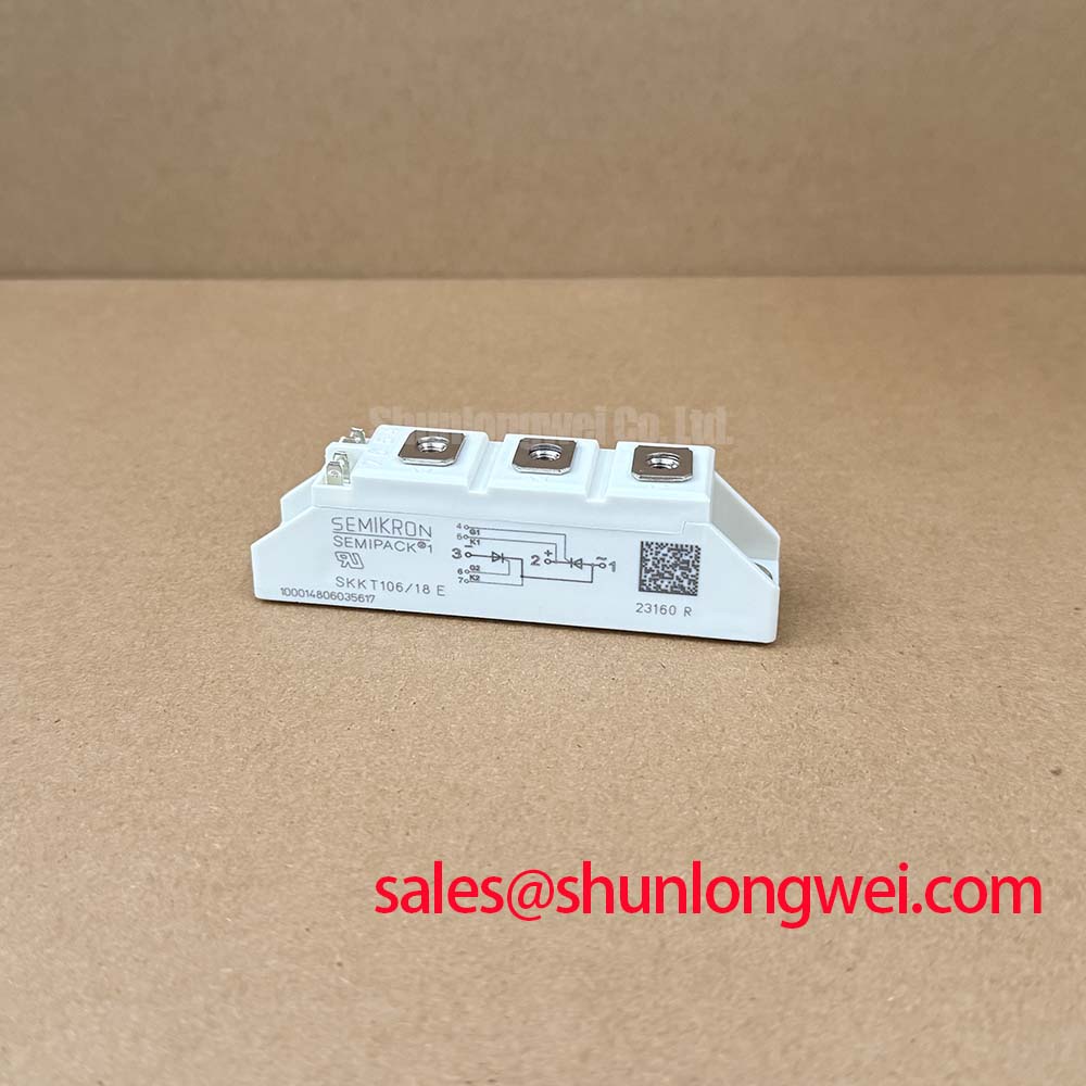
Before fitting the SKKT56/06D, isolate the equipment, confirm the module marking against the service bill of materials, and inspect the heatsink contact surface for burrs, oxidation, trapped debris, or uneven thermal compound left by the removed assembly. This Semikron thyristor module is rated at VDRM/VRRM 600V and ITAV 60A at a 74°C case temperature, so replacement assessment begins with confirming that the original converter’s voltage class, current demand, cooling arrangement, and terminal topology remain unchanged.
The SKKT56/06D is a thyristor module rather than a high frequency transistor switching module. Its commutation behaviour must therefore be assessed from the thyristor bridge topology, line inductance, load characteristics, gate control timing, and the associated commutation path. Reverse recovery current and recovery time are not specified in the supplied factory parameter set for this model, so they should not be assumed or assigned numerical values during repair planning. Engineers should review the original converter waveform, especially where line commutation, transformer leakage inductance, or freewheeling paths influence voltage stress.
Its factory specified critical rate of rise of off state voltage of 500V/µs indicates dv/dt immunity against unintended triggering under the stated test conditions. In practice, this value should be treated as an official device boundary, not as a system immunity guarantee. Long busbars, uneven phase routing, loose terminals, and poorly positioned suppression components can create local transient behaviour different from the nominal supply waveform.
For rectifier equipment such as a high current green hydrogen electrolyzer DC power supply, route each power path with comparable conductor geometry where the topology permits. A low inductance and mechanically stable loop helps limit commutation overshoot, reduces unequal current stress between parallel paths, and makes oscilloscope measurements more representative. Gate wiring should be kept separate from power conductors where possible, with return paths arranged to reduce magnetic coupling into the trigger circuit.
💡 Pro Tip: Keep busbar routing physically symmetric around the controlled rectifier path, then verify turn off and commutation voltage margins with measured waveforms under the actual operating load.
The module’s ITRMS rating of 95A is the specified RMS current rating, while the average on state current rating remains 60A at the specified case condition. These ratings should not be treated as interchangeable. RMS current relates to thermal loading from the current waveform, while average current depends on conduction angle and rectifier duty. The system engineer should calculate the actual waveform dependent device current and validate case temperature under the intended cooling conditions.
Terminal connections require clean conductive interfaces, correctly sized lugs, and controlled tightening according to the original equipment documentation or the applicable Semikron mechanical drawing. A terminal that appears tight but has reduced contact area can add resistance, create localized heating, and distort current sharing in the surrounding rectifier assembly. This is particularly important when the module is part of a multi device bridge.
SKKT56/06D Operational Boundaries: Evaluating Surge Energy Dissipation and Clamping Volt Limits
The first electrical boundary to verify is the relationship between the converter’s peak line voltage and the 600V repetitive peak off state and reverse voltage rating of the SKKT56/06D. The factory specified 700V non repetitive peak off state and reverse voltage rating addresses short duration exceptional events, but it is not a repetitive operating target. A recorded transient approaching this value warrants investigation of the incoming supply, transformer coupling, contactor events, cable layout, and protective network before the replacement module is energized.
For AC input assemblies exposed to surge events, a metal oxide varistor and RC suppression arrangement can be evaluated as a Design Consideration. Their suitability depends on the actual source impedance, mains category, transformer arrangement, wiring length, expected surge environment, and the measured clamping behaviour of the installed system. Component selection should be verified against applicable system surge requirements, including the relevant IEC 61000 4 5 test plan where that standard applies to the equipment. The thyristor module itself should not be represented as independently certified to a system level EMC or surge standard.
The official surge current capability is ITSM 1500A for a 10ms half sine pulse. This is useful when evaluating non repetitive fault and inrush exposure, but it does not define unlimited overload tolerance. Surge performance is affected by initial junction temperature, pulse shape, preceding load, cooling condition, line impedance, and fuse clearing behaviour. A maintenance team should compare recorded fault conditions with the protection coordination of the original cabinet rather than relying on a single peak current reading.
The factory specified I²t value of 11,000A²s provides the essential electrical basis for semiconductor fuse coordination. The fuse should be evaluated as a coordinated protection element with the complete assembly, including busbar inductance, prospective short circuit current, contactor behaviour, and the clearing characteristic supplied by the fuse manufacturer. A general purpose branch fuse can have a materially different clearing response from a semiconductor fuse even when its nominal current marking appears similar.
Where an electrolyzer rectifier has repeated nuisance fuse operation, avoid attributing the condition immediately to the SKKT56/06D. Useful checks include phase balance, transformer secondary waveform symmetry, load side shorts, trigger board timing, cooling airflow or liquid loop performance, and evidence of loose power joints. A measured gate pulse referenced to the correct cathode path can help distinguish a control timing issue from an external commutation disturbance.
For a higher current thyristor module comparison during a documented equipment redesign, the SKKT 250/14E provides a separate specification reference. It should be assessed as an independent candidate only after engineers verify voltage rating, current waveform, isolation arrangement, mechanical interface, gate terminal arrangement, heatsink compatibility, and protection coordination. It is not an automatic replacement for the SKKT56/06D.
SKKT56/06D Circuit Protection & Reliability: Calibrating RC Snubber Network Optimization to Prevent Unintended Triggering
An RC snubber network can be evaluated to control rapid voltage transitions across the thyristor positions and to reduce ringing caused by transformer leakage inductance and power loop parasitics. This is a Design Consideration, not a fixed SKKT56/06D accessory requirement. The capacitor, resistor, wiring route, thermal dissipation, pulse duty, and insulation class must be chosen from the measured switching environment and verified in the complete converter.
The 500V/µs critical dv/dt rating gives a formal reference point when examining susceptibility to unintended turn on. If the module fires outside the intended gate sequence, engineers should first verify trigger pulse timing, gate return routing, phase reference integrity, commutation waveform shape, and unwanted coupling from adjacent conductors. A transient observed at the cabinet input may not match the transient appearing directly across the module terminals; probe placement and reference lead arrangement affect the validity of the measurement.
Series reactors or saturable magnetic components are sometimes used in controlled rectifier systems to manage current rise or commutation conditions. Their inclusion and value are determined by the wider system, including transformer characteristics, load regulation requirements, and fault protection coordination. There is no supplied factory parameter establishing a mandatory reactor arrangement for this specific module. Any modification should be bench validated at controlled power before it is placed into operational service.
Gate drive integrity deserves equal attention. A gate circuit with poor isolation reference, excessive common mode coupling, or a damaged pulse transformer or isolator can cause inconsistent firing that resembles a power device problem. Compare firing pulses across each controlled leg using an appropriate isolated measurement method, then examine whether timing changes with load, line phase, temperature, or contactor state. Do not infer device condition solely from a gate signal viewed at the driver board when the actual gate and cathode reference path has not been verified.
The thyristor module’s 3000V~ isolation voltage is an official specification between the electrical terminals and the module baseplate or heatsink under defined factory test conditions. Installation must preserve that boundary. Contaminated heatsinks, conductive thermal materials outside the intended contact zone, damaged insulation hardware, and altered mounting arrangements can compromise the assembly even where the module marking remains unchanged. System insulation testing should follow the equipment manufacturer’s service procedure and applicable safety requirements.
Where commutation losses, line side ringing, or harmonic current need wider topology context, Resonant Topologies in Home Appliances offers background on the influence of switching loops and resonant energy paths. The principles can assist waveform interpretation, although the final protection network for a line commutated thyristor rectifier must be validated against its own transformer, load, and control architecture.
SKKT56/06D Circuit Protection & Reliability: Calibrating Mechanical Mounting Torque Sequence and Thermal Contact Pressure
Thermal installation begins with a flat, clean heatsink and a controlled, even fastening sequence that brings the module base into uniform contact without twisting the housing. The official thermal resistance from junction to case is Rth(j c) 0.57K/W per thyristor element. This value describes the internal thermal path under specified conditions; it does not include thermal interface material, heatsink spreading resistance, airflow, liquid cooling performance, or cabinet ambient temperature.
Apply thermal compound only as required by the original assembly process, using a thin and uniform interface layer rather than relying on excess material to compensate for a damaged heatsink. The objective is consistent contact across the mounting surface. Tightening torque, fastener size, washer stack, thread condition, and tightening order should follow the module manufacturer documentation or the original equipment service instruction. No mounting torque is specified in the supplied factory data for the SKKT56/06D, so a numerical torque should not be imposed without the correct mechanical reference.
⚡ Safety Interlock Note: De energize, lock out, and verify discharge of the DC link and connected capacitors before removing power or gate connections from the module.
After installation, measure the practical thermal response during controlled commissioning. Compare heatsink temperature distribution, conductor temperature, phase current balance, trigger stability, and output ripple against the known equipment baseline where available. An unexpectedly hot connection can arise from several conditions, including uneven contact pressure, degraded cooling, insufficient conductor contact area, imbalanced firing, overload, or an external circuit fault. Use measurements to isolate the condition rather than assigning a single cause.
The ITAV 60A rating at 74°C case temperature makes the actual case temperature a central commissioning measurement. If the operating case temperature differs from the stated rating condition, the system engineer should assess the resulting thermal margin from the original Semikron documentation and measured current waveform. The Semikron SEMIPACK thyristor and diode module information is useful for identifying the relevant product family context, while the Semikron Danfoss official power electronics hub provides manufacturer level technical resources for further verification.