Content last revised on October 1, 2026
SKKT56-16D Circuit Protection and Reliability: Calibrating Turn On Current Rise Limiting
| Manufacturer | Semikron |
|---|---|
| Model | SKKT56-16D |
| Product category | Thyristor/Thyristor Module |
| Rated voltage | 1600 V Official Datasheet Specification |
| Rated current | 56 A Official Datasheet Specification |
| Package | Semipack Official Datasheet Specification |
Measure the gate and main terminal wiring against the original schematic, then inspect the firing waveform and load current with an isolated oscilloscope before changing the protection network. The SKKT56-16D is a Semikron thyristor/thyristor module with a specified voltage rating of 1600 V and current rating of 56 A, housed in a Semipack package. These figures define the device rating boundary, not an automatic system operating limit under every thermal or switching condition.
For a medium frequency induction melting or hardening furnace, the RC snubber and any series saturable reactor should be evaluated against the actual commutation waveform. The design consideration is to limit unwanted dv/dt triggering and local di/dt stress while preserving the intended firing response. Select the snubber resistor and capacitor from measured transient energy, repetitive switching conditions, and the manufacturer’s coordination data. A saturable reactor should be assessed from its current waveform, saturation behavior, and thermal duty rather than selected from a generic current value.
Check every fuse coordination point against the Semikron fuse I2t table for the applicable device configuration. The semiconductor fuse clearing energy must remain compatible with the thyristor withstand capability during the fault duration. Junction temperature margin should be evaluated with the applicable transient thermal impedance network, using the real pulse profile and heatsink conditions. No field failure rate, service life, or cosmic ray tolerance is established here without a controlled source.
Field Alert: isolate the furnace supply and allow the DC link to discharge before removing gate or power wiring.
Preventing Spurious Faults: I2t Sub Cycle Melting Rating Guidelines for SKKT56-16D
Capture the first current excursion during a controlled protection test and compare the measured clearing interval with the selected semiconductor fuse coordination curve. A dead short can expose the module to a rapid energy pulse before the protective device opens, so fuse selection must consider prospective fault current, cable impedance, busbar arrangement, and the documented I2t withstand data for the exact circuit.
Use the marked module terminals and the original circuit diagram to confirm the thyristor paths before fitting a replacement. The Semipack package does not by itself define the furnace topology, gate circuit, fuse class, or permissible repetitive current. Designers should verify these items from the applicable Semikron documentation and the equipment manufacturer’s protection schedule.
Inspect the mounting surface, thermal interface, terminal condition, and clamping arrangement during the same service operation. Mounting torque is a design consideration governed by the module hardware and heatsink assembly; it should be taken from the relevant mechanical documentation rather than copied from a general-purpose value. The thermal path must be evaluated together with transient thermal impedance, pulse duration, ambient conditions, and cooling airflow.
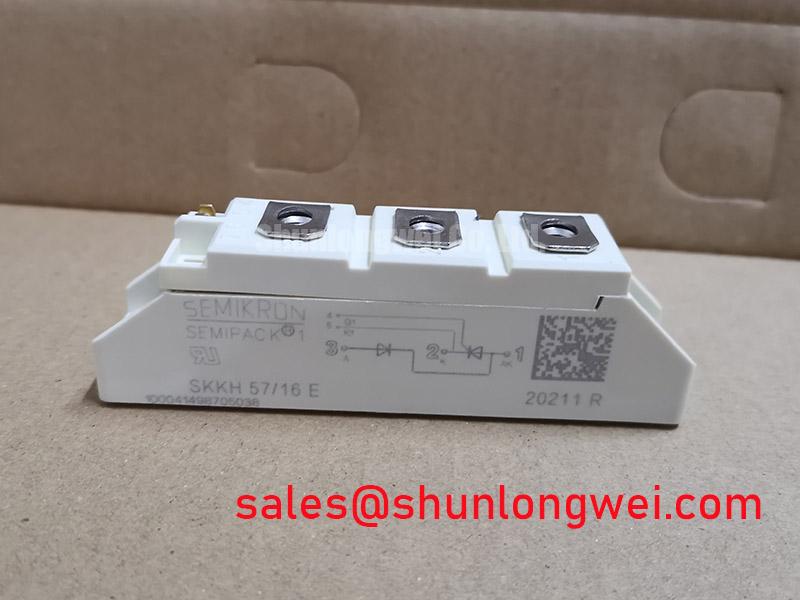
For related hardware evaluation, engineers may compare the circuit footprint and electrical function of SKKH57-16E, but any substitution requires terminal, rating, gate drive, mechanical, and protection verification.
Assembly Integrity and Layout Architecture: Implementing Harmonic Current Injection and Line Filter for SKKT56-16D
Probe the AC input current and DC output waveform at several firing angles while checking gate timing against the marked control terminals. The measured waveform should be compared with the intended AC to DC conversion behavior, power factor target, and reactive power limits of the furnace supply. Firing angle changes can alter current distortion and commutation stress, so the line filter must be evaluated with the complete transformer, reactor, cable, and load arrangement.
Keep the high current paths physically compact and symmetrical where the equipment layout permits, reducing avoidable parasitic inductance and unequal current sharing. This is an Engineering Recommendation, not an SKKT56-16D factory parameter. Verify peak transient voltage at the module terminals during switching tests, then assess the RC network, line reactor, and surge protection as a coordinated system.
The upstream rectifier or supply stage may be evaluated alongside SKKT 15/06D where the equipment architecture uses complementary power modules. Compatibility must be established from the actual schematic, terminal arrangement, voltage class, current duty, thermal path, and control sequence.
Semikron’s SEMIPACK thyristor and diode module information provides useful package level context. It does not replace the exact application documentation required for filter design, harmonic assessment, or EMC verification.
SKKT56-16D Operational Boundaries: Evaluating AC Input Transient Overvoltage Clamping Limits
Record the AC line transient at the module terminals and at the upstream protection device, then compare both traces with the voltage rating of 1600 V. MOVs, RC snubbers, line reactors, and semiconductor fuses should be selected from the actual supply system, prospective surge exposure, repetition rate, and coordination requirements. Surge immunity testing should follow the applicable equipment standard and test plan; the module itself must not be described as independently certified for whole equipment EMC compliance.
During commissioning, inspect the clamping waveform, leakage behavior, thermal loading, and recovery after each controlled surge test. The system integrator should verify whether the selected MOV and snubber remain within their own energy and voltage limits while keeping the thyristor junction transient below the documented device boundary. High altitude, cosmic ray effects, single event burnout, FIT values, and insulation lifetime require dedicated manufacturer or standards based evidence and should not be inferred from the 1600 V rating.
For broader system architecture context, the technical discussion in The Race for Efficiency can be reviewed alongside the equipment’s own thermal, switching, and protection test records. Semikron’s information on sintering technology may also help engineers understand package level thermal considerations without substituting for the specific SKKT56-16D datasheet.