

Content last revised on October 18, 2026
SKM600GA125D Incoming Inspection and Terminal Checks
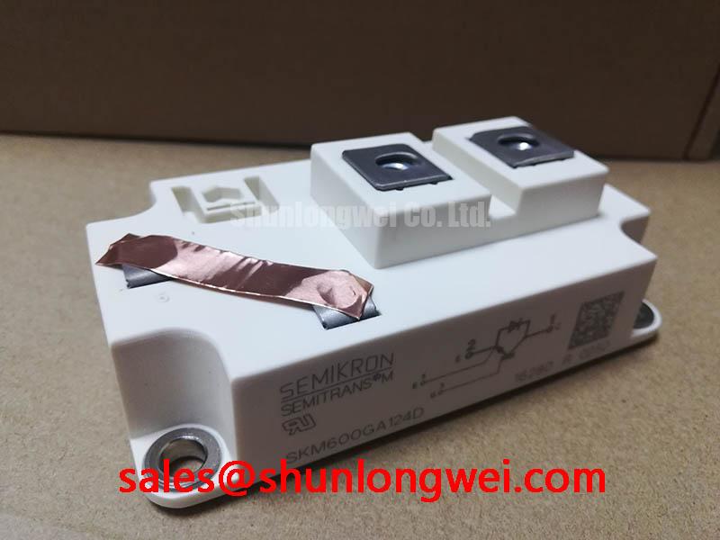
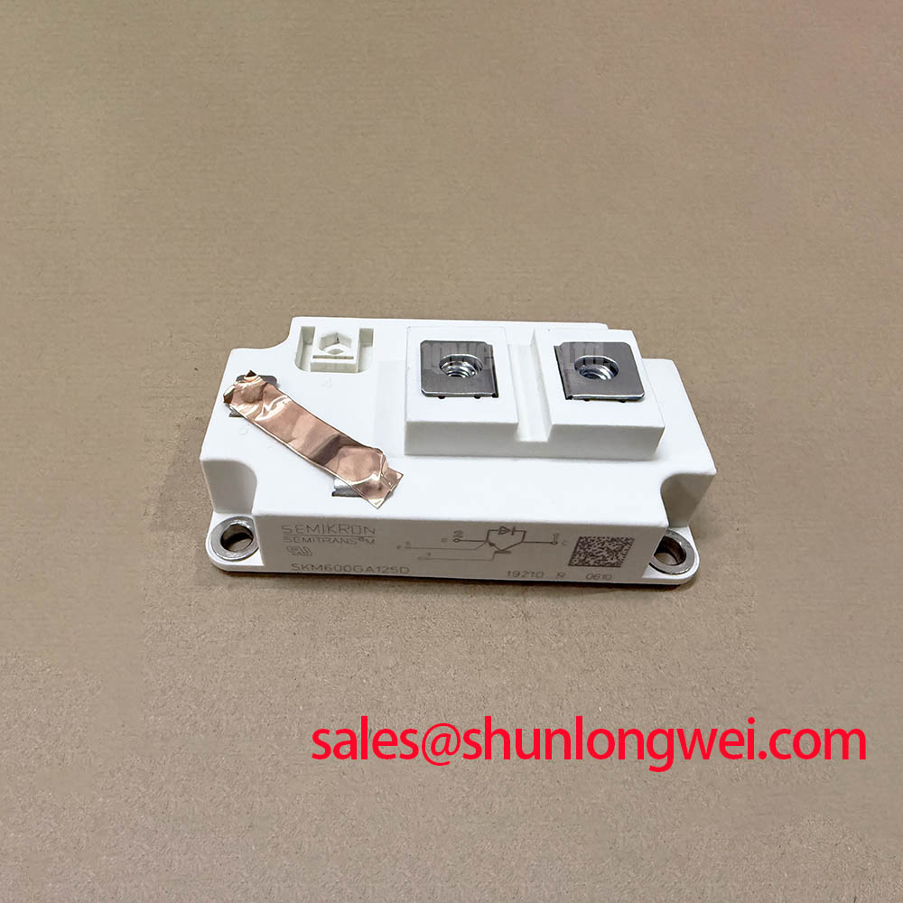
With the DC link discharged and the module isolated from surrounding circuitry, check terminal identification against the circuit drawing before recording diode-mode readings in both polarities. For the Semikron SKM600GA125D, the supplied official specifications identify a 1200 V voltage rating, a 600 A current rating under the specified datasheet conditions, and a Semitrans package. Keep those ratings alongside the incoming inspection record so that electrical screening and mechanical compatibility checks refer to the same device.
A handheld meter provides a useful cold-state comparison, but its test current does not reproduce operating conduction losses or blocking performance. Record instrument polarity, module temperature, and whether external connections remain attached. Compare readings with a documented reference under equivalent conditions, and investigate unexpected conduction through the gate connection before applying gate drive. Terminal numbers, insulation test conditions, mounting limits, and thermal curves belong to the exact manufacturer drawing and datasheet revision used for acceptance.
💡 Bench Tip: Keep the gate protected against electrostatic discharge and compare cold-state readings only after confirming that the DC link is discharged and the module is electrically isolated.
SKM600GA125D Circuit Protection & Reliability: Calibrating Junction-to-Case Thermal Network Simulation
Align the loss waveform with the measured case-temperature waveform before using a transient thermal model to assess pulsed loading. As a Design Consideration, separate conduction loss from switching loss and preserve the actual pulse spacing; averaging the entire event can conceal a junction-temperature peak. Position and document the case-temperature measurement consistently, because heatsink temperature cannot automatically substitute for the case reference used by a junction-to-case curve.
An Engineering Calculation can express the response to a constant power pulse as ΔTj-c(t) = P × Zth(j-c)(t), using the applicable manufacturer transient thermal impedance curve. Repeated or changing pulses require superposition or an equivalent thermal-network calculation. A multi-RC fit should reproduce the curve across the relevant pulse durations, rather than merely match its steady-state endpoint. Keep the junction-to-case network separate from the interface and heatsink network so their resistances are not counted twice.
For an integration assessment involving bidirectional battery charging and discharging, designers should examine the temperature excursion during current reversal and repeated load transitions. As an Engineering Recommendation, compare control strategies by their measured losses and calculated junction-temperature swing under the same cooling conditions. Smoother loading may reduce thermal cycling, but this does not establish a quantified service-life extension for the SKM600GA125D.
When measured temperatures diverge from the model, inspect sensor placement, interface contact, cooling conditions, and the loss estimate before adjusting fitted thermal coefficients. The manufacturer's Semikron Sintering Technology material provides context on packaging and thermal paths; it does not establish that this particular module uses that construction. Keep model inputs traceable to this device rather than borrowing thermal properties from another product family.
Transient Dynamics & Electrical Design: Baseplate Convexity Inspection on SKM600GA125D
Inspect the mounting surface for damage, contamination, and uneven contact before bringing the module against the heatsink. As a Design Consideration, assess baseplate profile and heatsink flatness using the applicable mechanical drawing and mounting procedure. An observed curvature needs interpretation against the permitted geometry; forcing the assembly flat with fasteners can introduce mechanical stress. Package identification alone does not establish baseplate material, acceptable convexity, or mounting-hole compatibility.
Follow the applicable tightening sequence with a calibrated tool, supporting the module evenly as the interface settles. A diagonal sequence is an assembly consideration where the manufacturer's mounting procedure specifies it. Thermal interface material should fill surface irregularities without creating an unnecessarily thick thermal barrier. Its application method and finished thickness depend on the module instructions, interface material, and surface condition; a generic thickness target should not become an acceptance specification for this part.
Verify collector, emitter, and gate connections against the exact terminal drawing before reconnecting busbars. As an Engineering Recommendation, check that busbar alignment does not pull terminals sideways and that cable restraint prevents vibration loads from reaching the connections. Review creepage and clearance at exposed terminals against the equipment's insulation coordination requirements, including contamination and enclosure conditions. Use the specified insulation-test connection arrangement and acceptance limits rather than selecting a test voltage from the blocking rating.
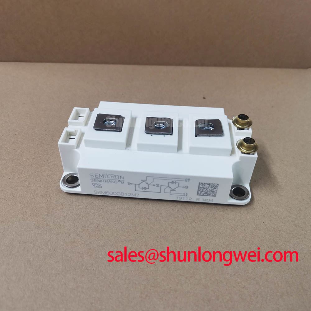
Replacement assessment should compare topology, terminal layout, mechanical dimensions, current conditions, and thermal performance together. The SKM300GA123D comparison provides related selection context, but it does not establish a direct replacement for the SKM600GA125D. Likewise, Semikron MiniSKiiP® Power Modules describes a separate product line whose mounting and connection arrangements should not be transferred to this Semitrans package.
SKM600GA125D Thermal-Electrical Optimization: High-Speed Semiconductor Fuse I²t Coordination
Compare the fuse's total clearing behavior with the prospective fault current, DC recovery voltage, and protected current path before evaluating coordination. As a Design Consideration, distinguish pre-arcing I²t from total clearing I²t: interruption continues after the fuse element melts. An IGBT's active short-circuit behavior also requires its own specified conditions and gate-protection response; a diode surge rating cannot serve as an interchangeable IGBT withstand limit.
Trace the discharge path from the DC-link capacitor through each possible fault location. A fuse positioned upstream of stored energy may interrupt incoming current while leaving a local capacitor discharge path intact. Designers should evaluate fuse placement, interruption capability, and containment at equipment level. Coordination cannot be reduced to choosing the smaller I²t number, and a clearing calculation alone does not demonstrate that module case rupture is prevented.
Gate-driver protection belongs in the same review. As an Engineering Recommendation, compare fault detection and controlled turn-off behavior with the switching waveforms measured at the module terminals. For optocoupler or digital-isolator interfaces, investigate common-mode transient immunity alongside driver supply disturbance, return-path coupling, and gate-loop layout. A false command or protection event can have several contributors; correlate logic-side signals with local gate voltage before assigning a cause.
Where a MOV participates in overvoltage protection, assess its clamping behavior, absorbed energy, and connection inductance against the actual transient. Its coordination with a fuse depends on the fault path and the protection objective. A complementary rectifier such as SKKE162/18 belongs to a separate circuit assessment, including polarity, current duty, and protection requirements. Mentioning both devices does not establish a matched rectifier and switching-module combination.
Transient Dynamics & Electrical Design: Cosmic Ray Robustness and Voltage Derating on SKM600GA125D
Record the maximum sustained blocking voltage and switching overshoot at each device position before considering altitude-related reliability. As a Design Consideration, terrestrial-neutron exposure and semiconductor susceptibility require application-specific assessment; altitude alone cannot supply a model-specific single-event burnout rate. A useful quantitative evaluation needs manufacturer susceptibility information, the electrical operating profile, and an identified environmental model.
Keep cosmic-ray assessment separate from insulation coordination. Both can influence a high-altitude installation, but they address different mechanisms and require different evidence. The 1200 V blocking rating is an electrical boundary, not a published FIT curve or an altitude qualification. Establishing a voltage-derating curve for SKM600GA125D therefore requires device-specific reliability evidence rather than a percentage inferred from its nameplate rating.
For compatibility assessment in a utility-scale 1500 V central photovoltaic inverter, examine the complete switching topology and the voltage imposed on each semiconductor. A 1200 V device cannot directly block a 1500 V bus. Any proposed use within a multilevel arrangement requires verification of voltage sharing, commutation states, startup behavior, and fault conditions. The system designation alone establishes no compatibility.
The Industrial Applications reference offers broader integration context for the review. As an Engineering Recommendation, retain measured blocking-voltage peaks, operating conditions, and the applicable manufacturer limits in the equipment acceptance record. Resolve an excessive peak through the circuit's commutation path, clamping arrangement, or operating conditions, then repeat the measurement at the affected device position.