

Content last revised on September 10, 2026
Thermal Cycling Degradation of Polarizer Adhesives & Sealant Gasket Integrity
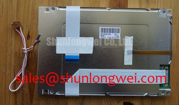
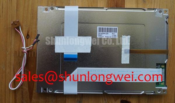
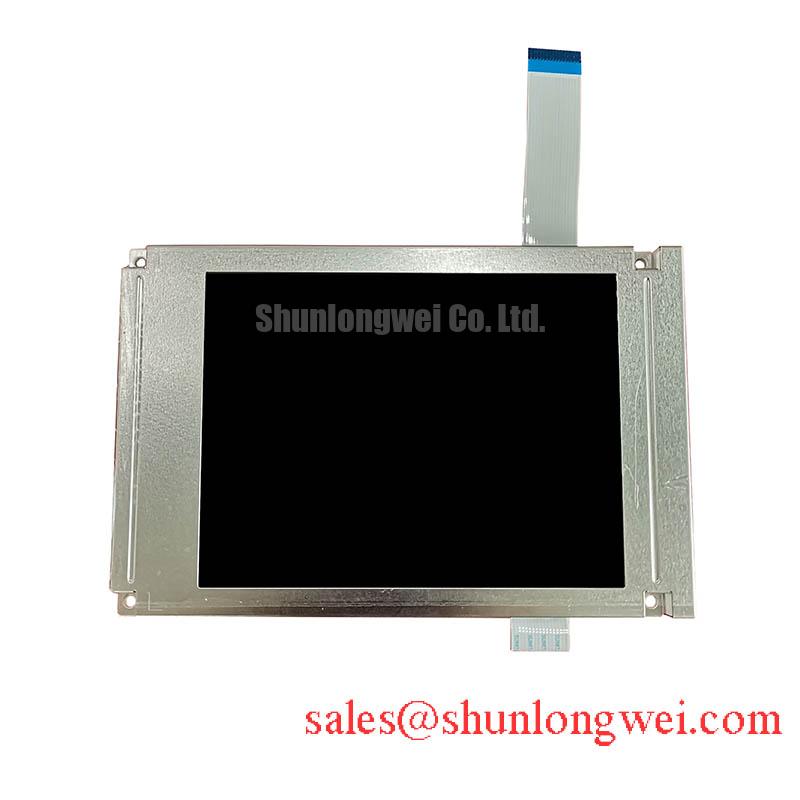
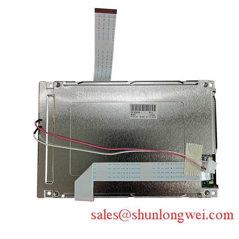
Begin incoming inspection by comparing the SX14Q004-ZZA marking with the original service record, then check the TFT-LCD module for edge damage, sealant irregularities, connector contamination, and visible polarizer defects before applying power. The available factory context identifies this product as an Industrial Grade LCD/HMI Panel manufactured by KOE / Hitachi, supplied as a TFT-LCD Display Module. Interface, optical, dimensional, and electrical values should be confirmed against the original panel documentation before installation.
| Model | SX14Q004-ZZA |
| Manufacturer | KOE / Hitachi |
| Product category | Industrial Grade LCD/HMI Panel |
| Package or assembly | TFT-LCD Display Module |
| Specification status | Verify against the original factory documentation |
For equipment exposed to cold starts and repeated cabinet temperature changes, inspect the display perimeter before functional testing. Look for lifting, whitening, edge separation, or contamination around the viewing area and frame. These observations do not identify a single failure mechanism by themselves, but they can justify closer review of the enclosure, compression points, and environmental history.
Liquid crystal viscosity can increase at sub-zero temperatures, so a slower gray-to-gray transition or temporary image trailing should be evaluated against the original panel behavior and the equipment warm-up profile. The supplied product information does not confirm a qualified operating range from −30°C to +85°C; those limits must not be assigned to SX14Q004-ZZA without the applicable factory datasheet. If the module is being considered for a marine radar or navigation bridge console, designers should assess heater control, condensation prevention, gasket compression, and salt-laden airflow as system-level conditions.
For high-EMI installations, differential routing should preserve the intended characteristic impedance and minimize pair skew. A 100 Ω ± 10% differential target and a skew budget of 50 ps or less may be used only as a Design Consideration when supported by the host interface documentation. The integrator must verify the actual interface type, connector pinout, and signal requirements for this model.
Polarizer Durability & Optical Retardation Film Inspection under Direct Industrial Lighting
Inspect the panel under controlled illumination and then under the lighting expected at the installation site. Check for uneven haze, local discoloration, scratches, pressure marks, and viewing-angle changes while displaying neutral gray and full-color images. TN, IPS, and MVA optical behavior must not be assumed from the model number, and the supplied factory parameters do not confirm a symmetric viewing cone of 85°/85°/85°/85°.
Anti-glare performance is also dependent on the complete optical stack, front window, ambient reflections, and viewing geometry. The available official context does not specify a surface treatment, contrast ratio, or performance at 50,000 lux. When evaluating the unit for outdoor marine equipment, measure readability with the final cover, bezel, and lighting arrangement in place rather than relying on a generic display rating.
Backlight service evaluation should compare luminance uniformity and dimming response at the intended driver settings. A claimed decay point such as 50,000 hours to 50% brightness requires a manufacturer source and defined test conditions; it is not an official parameter supplied here. The system integrator should verify whether the replacement module matches the existing constant-current driver and dimming control method.
Controlled 100-Ohm Differential Impedance Flex Routing to Suppress High-Frequency Jitter
Before connecting the module, document the original cable orientation and inspect the flex contact area for bent contacts, abrasion, or incomplete insertion. Do not assume that SX14Q004-ZZA uses a particular LVDS or TTL arrangement. The required supply voltage, power sequencing, connector assignment, and data format must be verified from the original panel documentation.
Where a differential interface is confirmed, route the pair as a controlled transmission path with consistent reference geometry and minimal discontinuities. JEIDA and VESA mapping are not interchangeable assumptions; incorrect bit ordering can produce color errors, unstable images, or split-screen artifacts even when the panel powers correctly. A proposed supply rise-time window such as 0.5 ms to 10 ms remains a host-system design condition unless listed in the applicable panel specification.
💡 Pro Tip: Disconnect power before inserting or removing the display cable, and verify the cable keying before the first powered test.
For an engineering comparison involving another industrial display, review TX23D11VM2BAA only after checking active area, resolution, mounting geometry, interface mapping, and backlight control compatibility. A similar category does not establish a drop-in replacement.
Incoming Benchtop Inspection: COG/TAB Anisotropic Conductive Film Integrity
Use a three-stage primary-color test with red, green, and blue screens, followed by white, black, and neutral gray images. Record fixed-line defects, intermittent columns, color contamination, and areas that change when the frame is gently observed without applying mechanical pressure. A 45-degree flashlight inspection can help separate surface reflection, backlight non-uniformity, and localized driver-line symptoms, but it cannot independently confirm a COG or TAB defect.
Fine horizontal or vertical lines should be compared with the known-good signal path while monitoring connector seating and host timing. If the fault changes with temperature, allow the panel to stabilize and repeat the test; low-temperature liquid crystal response may lengthen without proving permanent damage. Heater-strip control, if present in the host assembly, should be evaluated by the equipment designer according to the original service specification.
For broader guidance on panel selection, optical behavior, and industrial TFT integration, consult The Ultimate Guide to Industrial TFT LCD Technology. Any enclosure sealing, salt-fog protection, EMC performance, or insulation assessment remains the responsibility of the completed equipment. The display module itself should not be represented as independently certified for whole-system EMC or marine compliance.